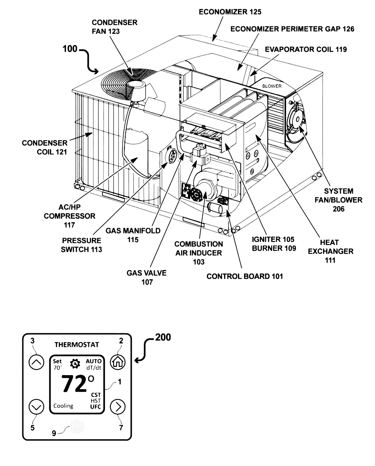
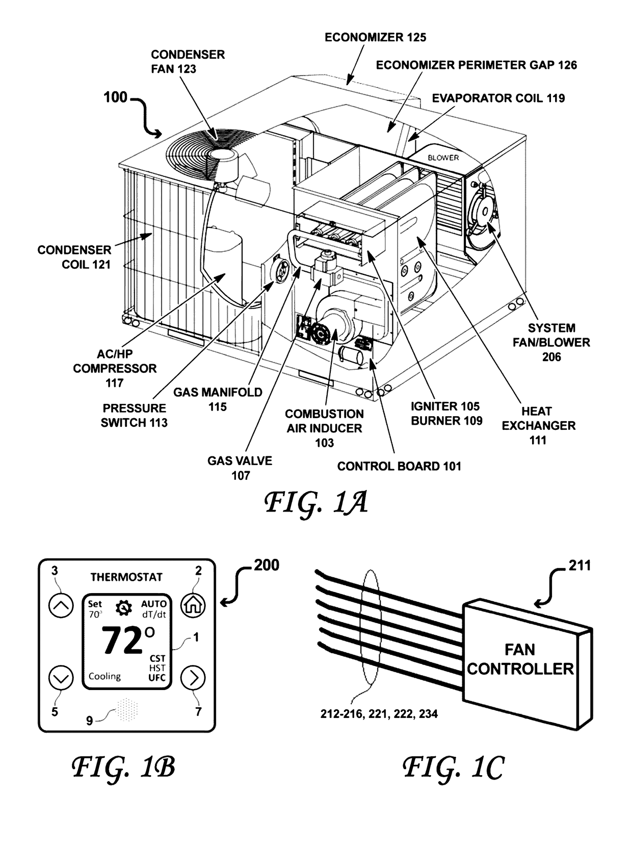
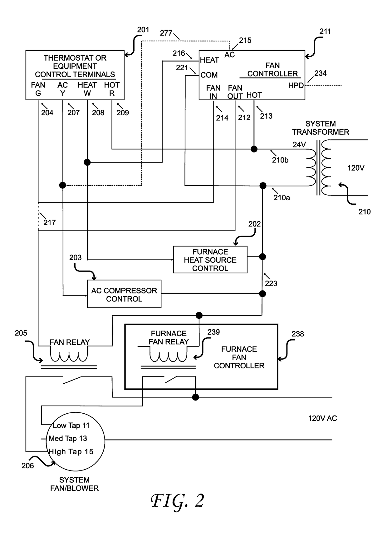
Fan Controller
Active Publication Date: 2017-04-27
LAU JAMES
View PDF0 Cites 29 Cited by
- Summary
- Abstract
- Description
- Claims
- Application Information
AI Technical Summary
Benefits of technology
[0077]FIG. 20 shows a graph of total heating system power (kW) versus time of operation for a known fan control with constant fan operation during unoccupied periods of time causing over ventilation, constant fan power, short cycling of the heat source, and increased heating power consumption and a graph showing unoccupied fan-off control reduces fan and heating power consumption and short cycling according to an embodiment of the present
Problems solved by technology
Maintaining a lower heater ventilation fan speed results in increased heat soak within the heating system and the portion of the heat generated by the heat-source not delivered to conditioned space is lost to the environment.
Known gas furnace fan controllers recover some of this energy by providing a temperature delay or a fixed-time delay to extend fan operation after the furnace has been turned OFF.
Known fan-off delays leave a significant amount of unrecovered heating energy in the heat exchanger that is wasted and lost to the environment after the heat-source and the ventilation fan are tuned OFF.
This dec
Method used
View moreImage
Smart ImageViewing Examples
Examples
 PUM
 Abstract
Method for controlling an HVAC ventilation fan in heating or cooling mode and varying the fan-off time delay as a function of heat source or cool source operational time. Method for increasing heater ventilation fan speed from the low speed used for heating to the high speed used for cooling. Method for maintaining the heat pump reversing valve signal at the same position throughout the cool or heat source operational and extended variable fan-off time delay. Method for closing economizer dampers at the end of the cool or heat source operational time while continuing to operate the ventilation fan for an extended variable fan-off time delay.
Description
CROSS-REFERENCE TO RELATED APPLICATIONS[0001]The present application claims the priority of U.S. Provisional Patent Application Ser. No. 61 / 324,229 filed Apr. 14, 2010, and is a Continuation In Part of U.S. patent application Ser. No. 13 / 085,119 filed Apr. 12, 2011, and is a Continuation In Part of U.S. patent application Ser. No. 13 / 427,542 filed Mar. 22, 2012, and is a Continuation In Part of U.S. patent application Ser. No. 14 / 168,503 filed Jan. 30, 2014, and is a Continuation In Part of U.S. patent application Ser. No. 15 / 144,806 filed May 2, 2016, and is a Continuation In Part of U.S. patent application Ser. No. 15 / 251,978 filed Aug. 10, 2016 which applications are incorporated in their entirety herein by reference.BACKGROUND OF THE INVENTION[0002]The present invention relates to a Heating, Ventilation, Air Conditioning (HVAC) fan controller device and in particular to a circuit obtaining signals from thermostat or equipment control terminals and providing signals to control th...
Claims
Login to View More Application Information
Patent Timeline
 IPC IPC(8): F24F11/053F24H9/20F24F11/76
CPCF24F11/053F24F2011/0002F24H9/2064F24H9/2071F24D19/1084F24D19/1087G05D23/1951F24F11/46F24F11/77Y02B30/70F24F11/76
Inventor MOWRIS, ROBERT J.WALSH, JOHN
Owner LAU JAMES
Features
- R&D
- Intellectual Property
- Life Sciences
- Materials
- Tech Scout
- Unparalleled Data Quality
- Higher Quality Content
- 60% Fewer Hallucinations
Learn More Browse by: Latest US Patents, China's latest patents, Technical Efficacy Thesaurus, Application Domain, Technology Topic, Popular Technical Reports.
© 2025 PatSnap. All rights reserved.Legal|Privacy policy|Modern Slavery Act Transparency Statement|Sitemap|About US| Contact US: help@patsnap.com


