
Simplified topology for HID lamps

a topology and simplified technology, applied in the direction of electric variable regulation, process and machine control, instruments, etc., can solve the problem of limit on harmonic current drawn, and achieve the effect of reducing the cost of the overall solution

Inactive Publication Date: 2006-07-18
INTERNATIONAL RECTIFIER COEP
View PDF8 Cites 24 Cited by
  • Summary
  • Abstract
  • Description
  • Claims
  • Application Information

AI Technical Summary

Benefits of technology

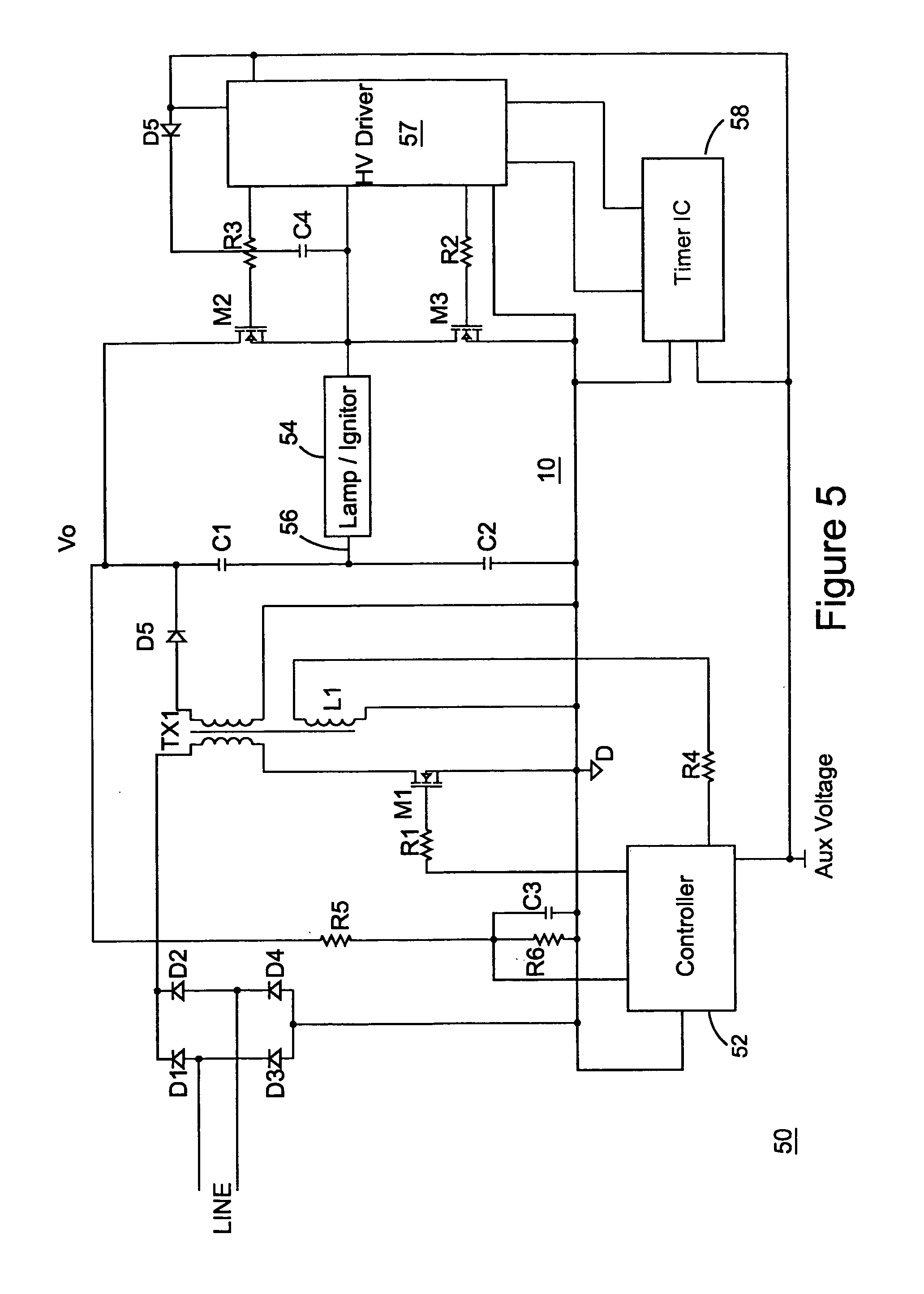
"The present invention provides a ballast for driving an HID lamp that provides low frequency modulation, constant power to an inverter section and draws sinusoidal current from the input main power supply. The power converter detects conditions in a transformer used to convert input power to supply the inverter. The power converter control also senses an output voltage of the inverter to ensure constant power is delivered to the load. Sensing the inverter voltage output also permits the control to react to the lamp ignition. The voltage sense of the inverter output provides all the feedback needed to maintain constant power at the lamp. The various rules used to drive the simplified HID ballast are established based on a sense of the voltage output of the inverter. The invention also includes a ballast power converter driven in critical mode with a variable switching frequency and a half bridge inverter configuration by a high voltage driver coupled to an oscillator or timer IC. The use of two capacitors split across the lamp load permits the use of the half bridge topology to avoid a full bridge switching configuration to reduce the cost of the overall solution. Other features and advantages of the invention include a simplified design that can be used with a variety of HID lamps and a flexible control that can adapt to changes in output voltage."

Problems solved by technology

In addition to the practical limitations illustrated by the suggestions of the lamp manufacturers, international regulations call for a limit on the harmonic current drawn by a converter connected to an HID lamp.

Method used


Image

  • Simplified topology for HID lamps
  • Simplified topology for HID lamps
  • Simplified topology for HID lamps

Examples


Embodiment Construction

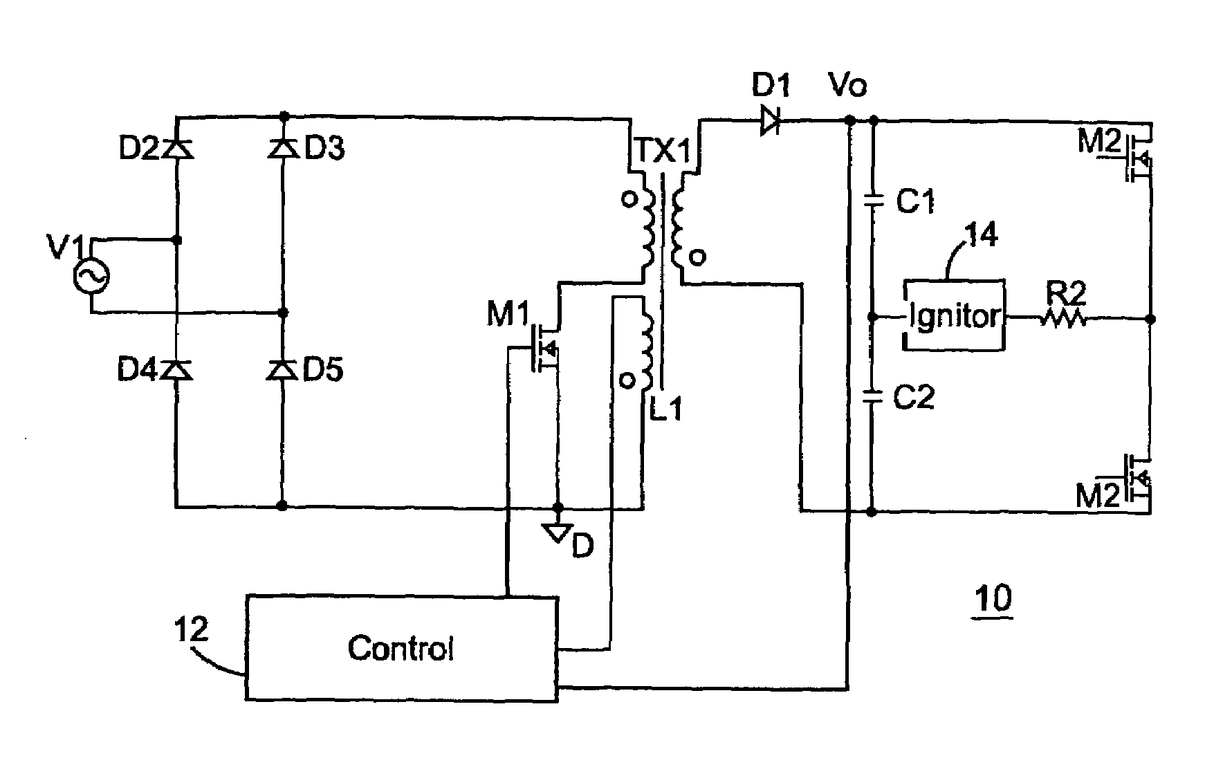
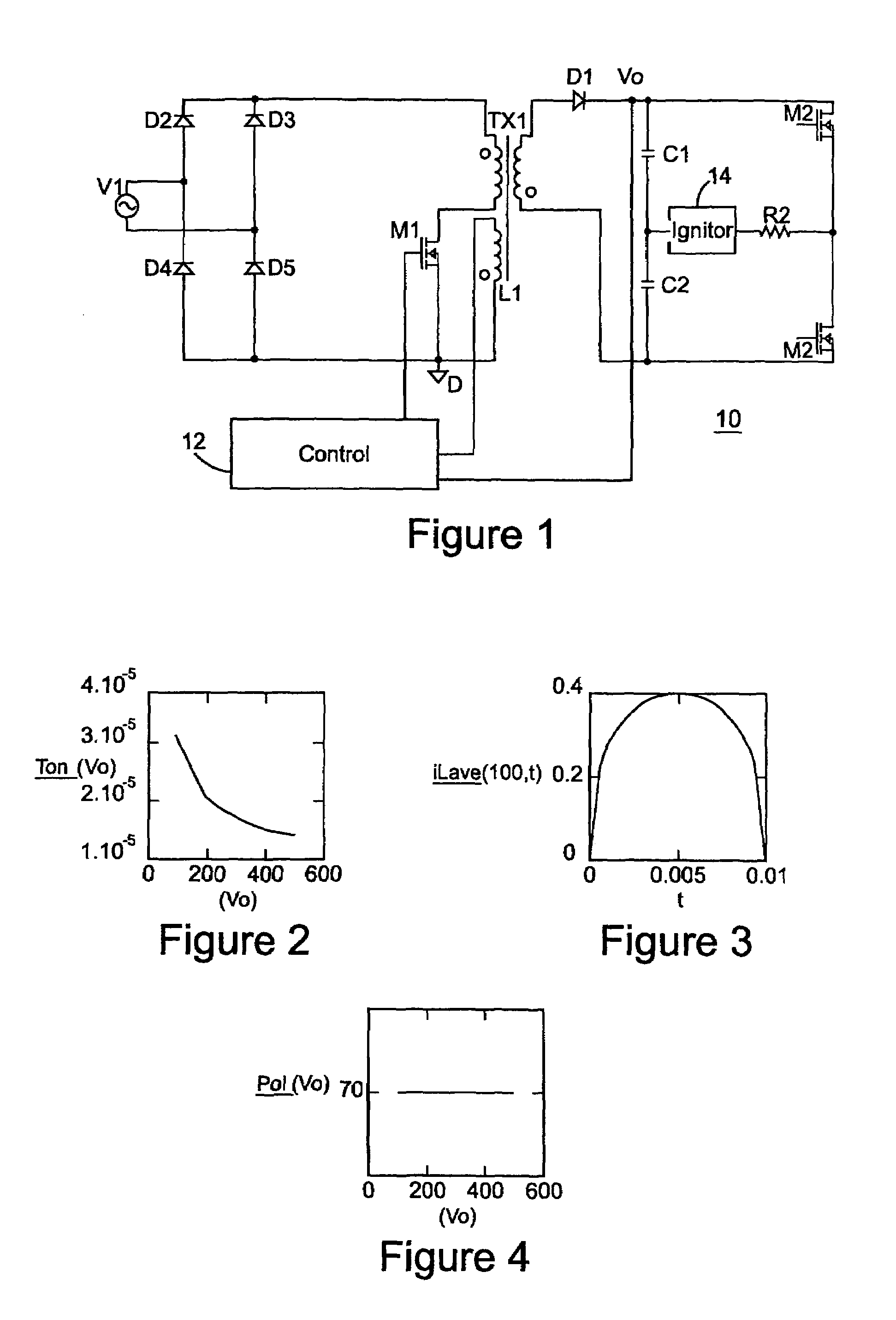
[0024]Referring now to FIG. 1, an abstract circuit diagram of an electronic ballast control for an HID is illustrated generally as circuit 10. Circuit 10 includes a transformer TX1 that receives a full wave rectified signal from the diode bridge consisting of diodes D2–D5. In accordance with a known result, if a flyback converter is operated in critical conduction mode, the output of such converter provides constant power if the main switch is driven with a constant on interval and a variable off interval, while receiving a constant input voltage. With these conditions, the output voltage and output current of the flyback converter follow a constant power law.

[0025]However, when the voltage received by the flyback converter is not constant, but rather a fullwave rectification signal like that delivered by the diode bridge consisting of diodes D2–D5 in circuit 10, a different control approach is taken. A modified control approach is especially indicated if constant power is to be del...


PUM


Abstract

An HID ballast includes a flyback power converter with a simplified topology that permits power factor correction while supplying constant output power to drive an inverter supplying low frequency modulated power to the HID lamp. A switch is coupled in series with a transformer in the power converter to control current through the transformer to provide constant output power. The off time of the switch contributes to controlling the power factor of the ballast circuit. The transformer is operated in critical conduction mode, with an indication of zero current in the transformer used to determine the control for the switch. An output of the flyback power converter provides a feedback signal to obtain constant power output based on switching intervals applied to the switch coupled to the transformer. This simplified topology reduces part counts while providing a robust control that can be flexibly applied to a number of HID lamps.

Description

RELATED APPLICATION[0001]This application is based on and claims benefit of U.S. Provisional Application No. 60 / 507,637, filed Sep. 30, 2003, entitled Simplified Topology for HID Lamps, to which a claim of priority is hereby made.BACKGROUND OF THE INVENTION[0002]1. Field of the Invention[0003]The present invention relates generally to ballasts for HID lamps, and related more particularly to a simplified topology for a ballast to drive an HID lamp.[0004]2. Description of Related Art[0005]High intensity discharge (HID) lamps are highly desirable for commercial markets due to their superior light efficiency in terms of lumens produced per watt and the variety of power ranges in which they are available. As HID lamp technology as developed, manufacturers and ballast designers have come to focus on reliability and efficiency in providing a robust and simple HID lighting system. For example, lamp manufacturers typically suggest that an HID lamp be driven in an AC mode, at a low frequency ...

Claims


Application Information

Patent Timeline
Patent Type & Authority Patents(United States)
IPC IPC(8): G05F1/00H05B37/02H05B41/24H02M3/28H05B41/288
CPCH05B41/2886H05B41/2888Y02B20/202Y02B20/00
Inventor BOCCHIOLA, CESARE
Owner INTERNATIONAL RECTIFIER COEP
Learn More