Power transmission method and power transmission apparatus

a technology of power transmission and transmission method, which is applied in the direction of electric power transmission ac network, dc source parallel operation, electrolytic capacitor, etc., can solve the problems of increasing the cost of the apparatus manufactured with this principle, and increasing the cost of the apparatus

Active Publication Date: 2010-12-30
VACON OY
View PDF11 Cites 21 Cited by
  • Summary
  • Abstract
  • Description
  • Claims
  • Application Information

AI Technical Summary

Benefits of technology

[0009]The aim of this invention is to achieve a new kind of method, with which the aforementioned drawbacks are avoided and with which a technically advantageous multistep voltage pattern is enabled in the connection of both an electric machine and an AC network (power transmission network). Owing to the multistep attribute, e.g. a

Problems solved by technology

A number of problems are attached to a serial circuit, such as e.g. the fact that the insulating strength of modular-type low-voltage power semiconductor switches (e.g. 1700 V voltage endurance) is not sufficient for medium voltages, for which reason awkward mechanical constructions that increase costs are needed for arranging adequate insulations.
These types of components are generally quite expensive owing, among other things, to the demanding manufacturing process and the small manufacturing quantities, which also incre

Method used


Image

  • Power transmission method and power transmission apparatus
  • Power transmission method and power transmission apparatus
  • Power transmission method and power transmission apparatus

Examples


Embodiment Construction

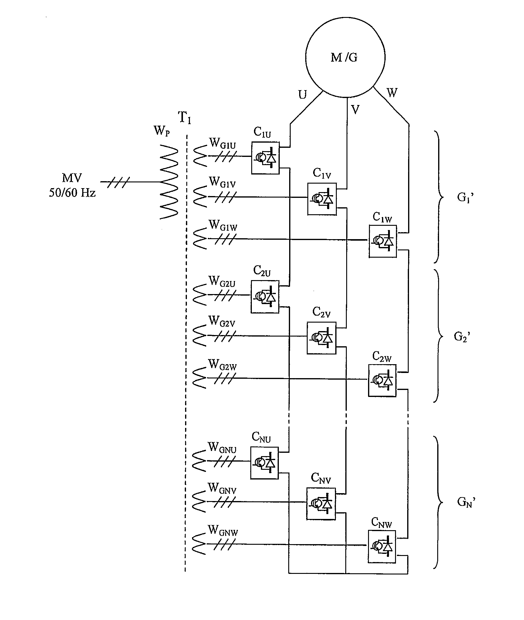
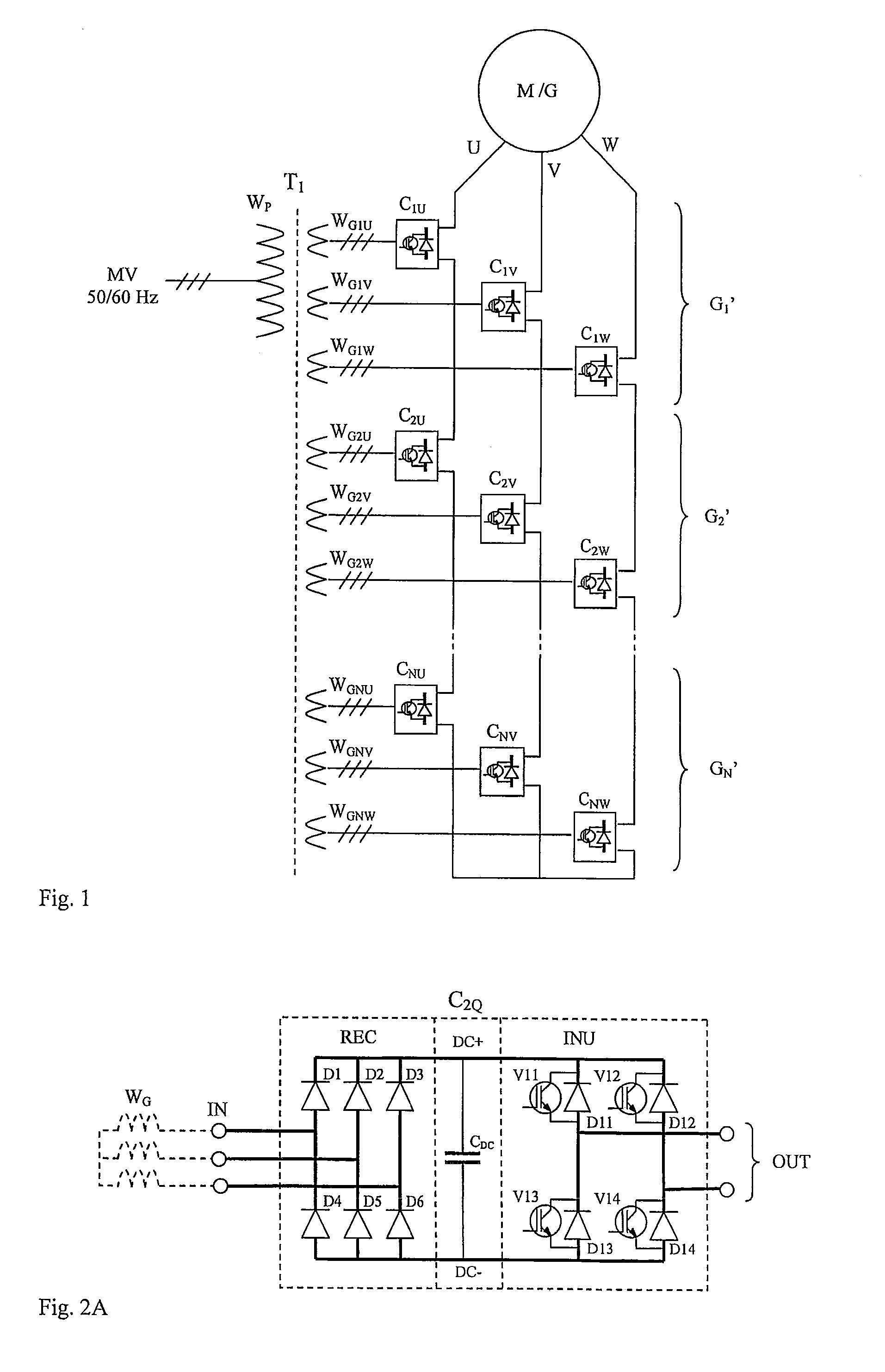
[0031]FIG. 1 describes a prior-art basic circuit of a medium-voltage so-called cascade-connected frequency converter, the operation of which type of circuit is known from e.g. patent publication U.S. Pat. No. 5,625,545. It comprises both the medium-voltage supply voltage MV, the frequency of which is normally 50 Hz or 60 Hz, and the medium-voltage connection voltage of the electric machine M / G, which can be adjusted in frequency. The frequency converter comprises low-voltage power cells, many of which are connected in series in each phase U, V, W. The power cells are connected to a common transformer T1, the 3-phase primary winding WP of which is connected to the supplying medium-voltage network MV, and which transformer comprises a separate 3-phase low-voltage secondary winding WG1U-WGNW for each power cell. To reduce the harmonics produced in the supply network, the secondary voltages can be phase-shifted with regard to each other, e.g. such that the voltages of the winding group ...


PUM


Abstract

Method and apparatus for controlling an apparatus transmitting power between two electricity networks or between an electricity network and a polyphase electric machine (M/G), which electricity networks can be polyphase alternating-current networks or one of them can be a single-phase direct-current network, and which apparatus comprises low-voltage power cells (C), which comprise a single-phase output connection (OUT). The power cells also comprise a single-phase input connector (IN), the power cells are arranged into groups (G1-GN, GP1-GPN1, GS1-GSN2, G1′″-GN′″) such that at least one power cell per each phase of the electricity network or of the electric machine belongs to each group, and the input terminals (IN) of all the power cells belonging to the same group are connected to a common transformer, which transformer comprises its own separate winding that is galvanically isolated from the others for the power cell connected to it. The controllable power semiconductor switches connected to the input connectors (IN) of all the power cells supplying power to the same transformer are controlled essentially cophasally with a 50% pulse ratio.

Description

FIELD OF TECHNOLOGY[0001]The present invention relates to a method and an apparatus for transmitting power between a polyphase electric machine (motor or generator) that operates with alternating current (AC) and a power transmission network, which can be either a polyphase alternating-current (AC) network or a direct-current (DC) network. The invention can also be applied to power transmission between different networks, such as e.g. from a DC network to a polyphase AC network, or between AC networks of different voltages. More particularly, the invention relates to power transmission in a medium-voltage environment, in which both the electric machine and the power transmission network are medium-voltage.PRIOR ART AND DESCRIPTION OF PROBLEM[0002]A medium-voltage network refers to an electricity distribution network of over 1 kV that is used in the transmission of electrical energy e.g. between a high-voltage (over 36 kV) main grid and a low-voltage (below 1 kV) consumer network. El...

Claims


Application Information

Patent Timeline
IPC IPC(8): H02P27/06H02J3/34H02M5/458H02M1/00H02M7/49
CPCH02M5/225H02M2001/0077H02M2001/0074H02M7/49H02M1/0074H02M1/0077H02J3/36H02M5/458H02M7/797
Inventor KOMULAINEN, RISTOSAREN, HANNU
Owner VACON OY
Why Eureka
Try Eureka