Safety platform scaffold apparatus

a safety platform and scaffold technology, applied in the field of scaffolds, can solve the problems of framers, who install roof trusses on the tops of vertical walls, and are subject to potential falls and other injuries, and achieve the effects of low manufacturing cost, convenient and efficient manufacturing and marketing, and durable and reliable construction

Inactive Publication Date: 2017-05-04
BROUGH JOHN
View PDF2 Cites 4 Cited by
  • Summary
  • Abstract
  • Description
  • Claims
  • Application Information

AI Technical Summary

Benefits of technology

[0020]It is another object of the present invention to provide a new and improved safety platform scaffold apparatus which may be easily and efficiently manufactured and marketed.
[0021]It is a further object of the present invention to provide a new and improved safety platform scaffold apparatus which is of durable and reliable construction.
[0022]An even further object of the present invention is to provide a new and improved safety platform scaffold apparatus which is susceptible of a low cost of manufacture with regard to both materials and labor, and which accordingly is then susceptible of low prices of sale to the consuming public, thereby making such safety platform scaffold apparatus available to the buying public.
[0023]Still yet a further object of the present invention is to provide a new and improved safety platform scaffold apparatus that keeps those installing roof trusses safe in a number of ways.
[0024]Still another object of the present invention is to provide a new and improved safety platform scaffold apparatus that can be readily assembled and disassembled at a work site.
[0025]Yet another object of the present invention is to provide a new and improved safety platform scaffold apparatus that is relatively light and easy to lift and lower, with respect to the top of a wall.

Problems solved by technology

It is well known in the building construction art that framers, who install roof trusses on the tops of vertical walls, are subject to potential falls and other injuries because they cannot readily tie themselves to the top of a wall upon which a roof truss is installed.

Method used


Image

  • Safety platform scaffold apparatus
  • Safety platform scaffold apparatus
  • Safety platform scaffold apparatus

Examples


Embodiment Construction

[0045]With reference to the drawings, a new and improved safety platform scaffold apparatus embodying the principles and concepts of the present invention will be described.

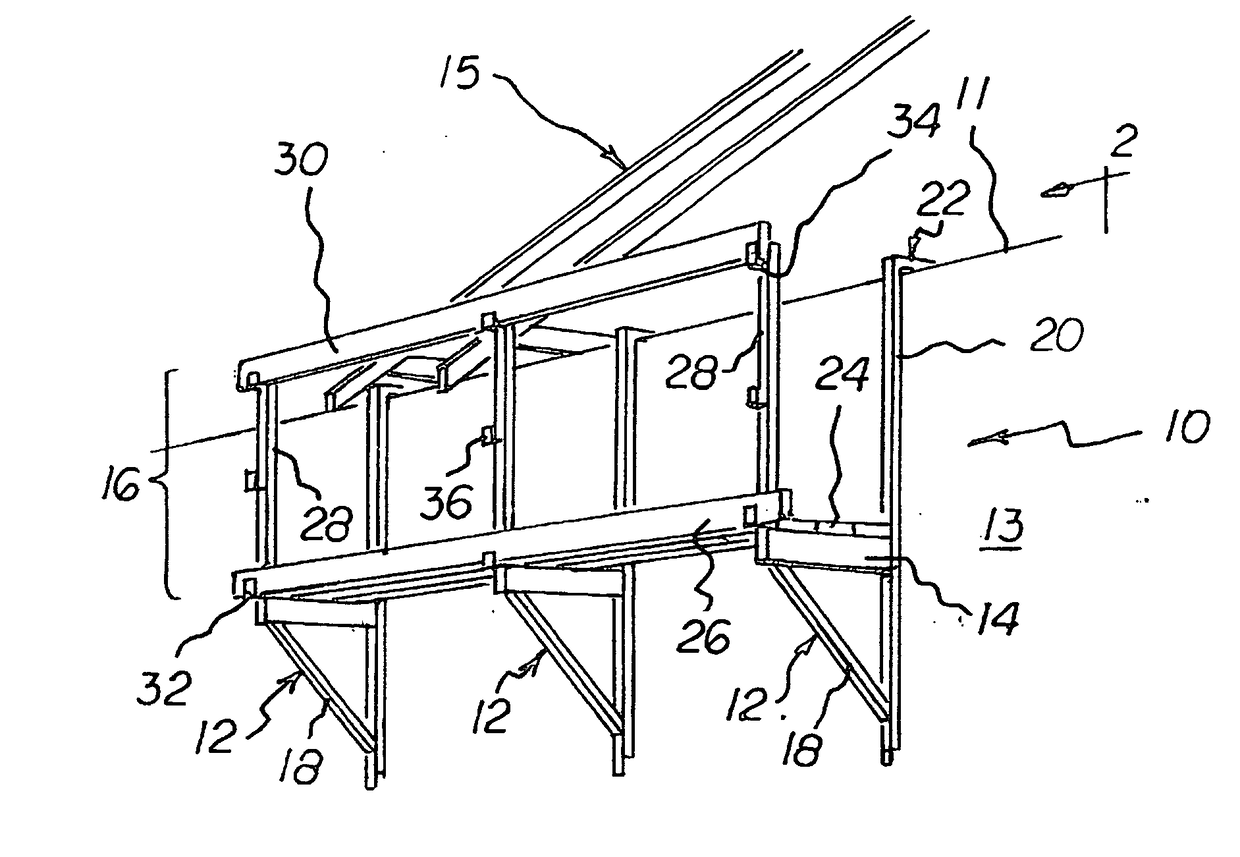
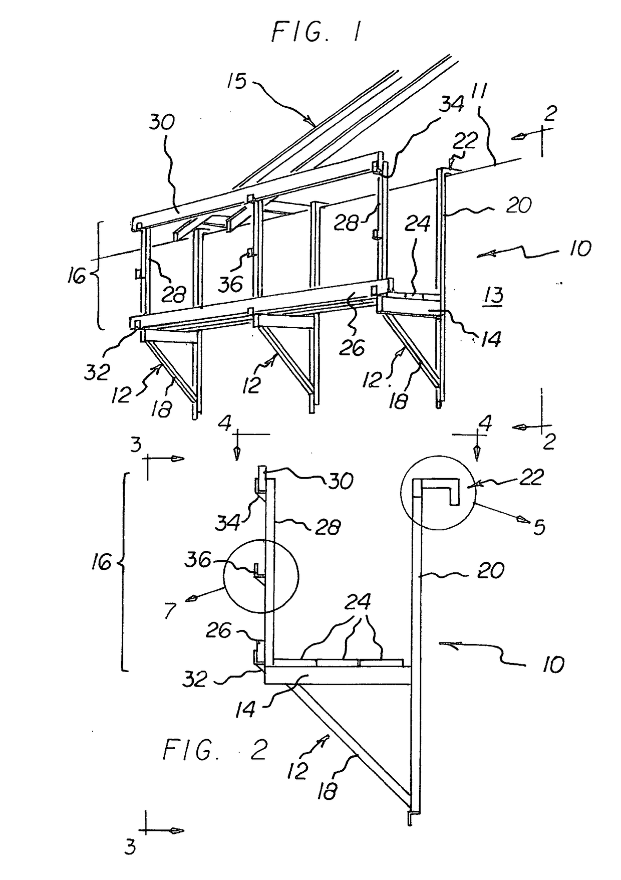
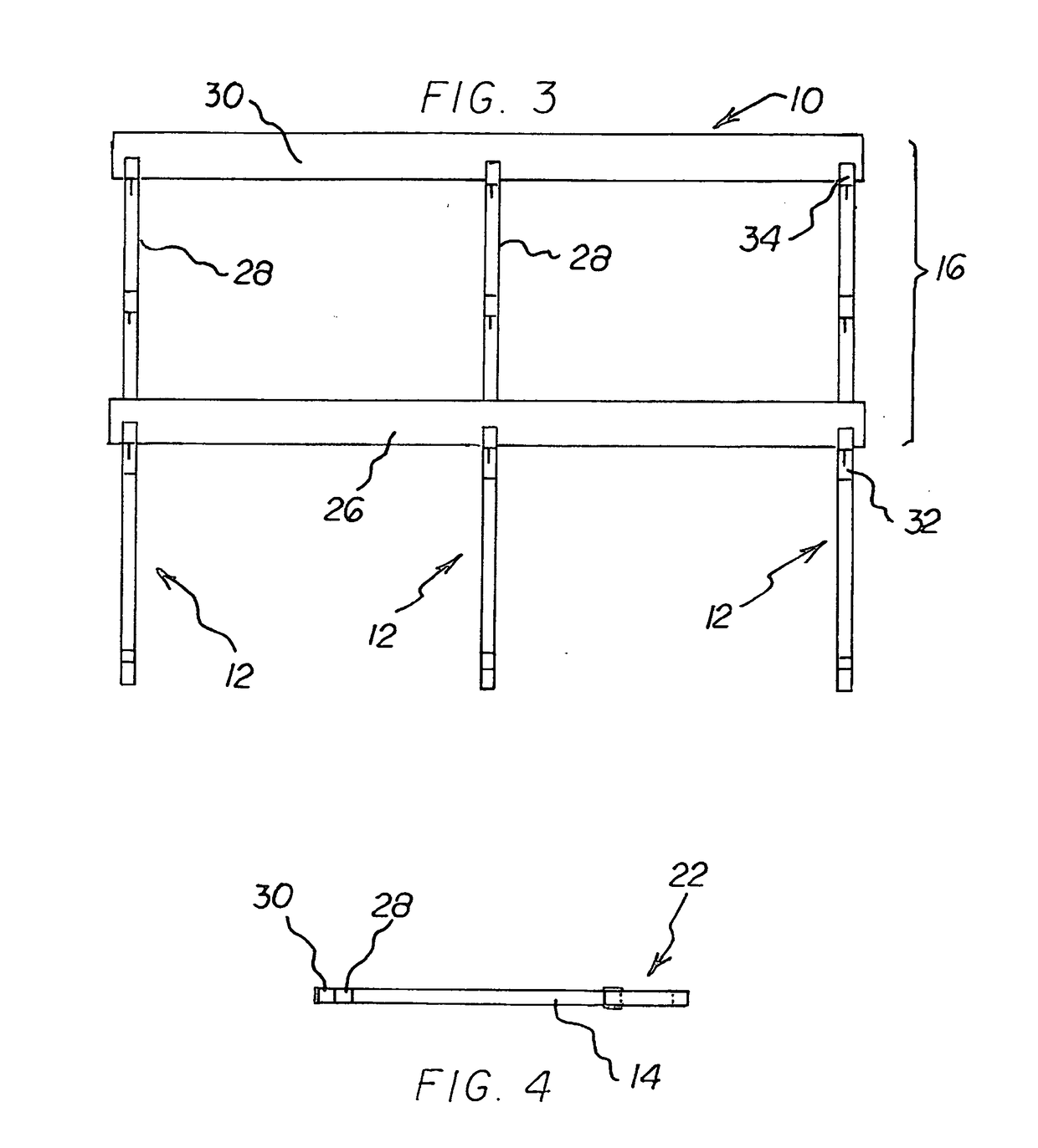
[0046]Turning to FIGS. 1-8, there is shown a first preferred embodiment of the safety platform scaffold apparatus of the invention generally designated by reference numeral 10. In each of the figures, reference numerals are shown that correspond to like reference numerals that designate like elements shown in other figures.

[0047]In the first preferred embodiment, safety platform scaffold apparatus 10 is provided for being supported by a wall 13 which has a wall top 11. The apparatus includes a plurality of wall-supportable units 12 for being supported by the wall 13. A plurality of floor members 24 are supported by the wall-supportable units 12, and a fence unit 16 is connected to the plurality of wall-supportable units 12.

[0048]Preferably, each of the wall-supportable units 12 includes a wall-contacting riser po...


PUM


Abstract

A safety platform scaffold apparatus is provided having a plurality of wall-supportable units, each with a floor support portion. A work platform is removably mountable on the floor support portions by suitable connectors affixed to the opposed ends of the platform. The opposed connectors are complimentary to each other so that they can be nested together on the same floor support portion thereby enabling a multiplicity of wall supportable units to be mounted on a wall with juxtaposed side-by-side platforms defining a smooth, flat, continuous work surface and wherein the platforms interlock with each other and the wall-supportable unit floor portions.

Description

RELATED APPLICATION[0001]The present application is a continuation-in-part of my prior pending application Ser. No. 14 / 121,567, filed Sep. 19, 2014, entitled “Safety Platform Scaffold Apparatus,” and claims priority based upon said prior, pending application for all purposes. By this reference, my prior pending application Ser. No. 14 / 121,567 hereby is incorporated in and made part of this application.BACKGROUND OF THE INVENTION[0002]1. Field of the Invention[0003]The present invention relates generally to scaffolds, and, more particularly, to scaffold especially adapted for a person who performs framing operations on a roof truss.[0004]2. Description of the Prior Art[0005]It is well known in the building construction art that framers, who install roof trusses on the tops of vertical walls, are subject to potential falls and other injuries because they cannot readily tie themselves to the top of a wall upon which a roof truss is installed. In this respect, it would be desirable if a...

Claims


Application Information

Patent Timeline
Patent Type & Authority Applications(United States)
IPC IPC(8): E04G3/20
CPCE04G3/20E04G3/22
Inventor BROUGH, JOHN
Owner BROUGH JOHN
Why Eureka
Try Eureka