Rotation detecting device

Active Publication Date: 2017-05-04
HIROSE ELECTRIC GROUP
View PDF3 Cites 2 Cited by
  • Summary
  • Abstract
  • Description
  • Claims
  • Application Information

AI Technical Summary

Benefits of technology

The patent describes a device that generates magnetic fields to detect rotational movement. By arranging magnets close to the rotating part, the magnetic flux is concentrated to pass through the part in a specific location. This allows for reversal of the magnetization direction, which improves the accuracy and reduces the size of the device. The device uses the large Barkhausen effect, which causes the magnetization direction to change quickly when the magnets pass through a specific location. The change in direction causes a pulse in the output of the device.

Problems solved by technology

If the coil 107 does not properly generate the pulse, it is difficult for the conventional rotation detecting device 101 to detect accurately the rotation of the rotational member 104.

Method used


Image

  • Rotation detecting device
  • Rotation detecting device
  • Rotation detecting device

Examples


first embodiment

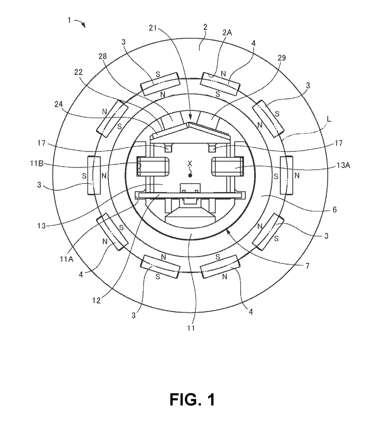
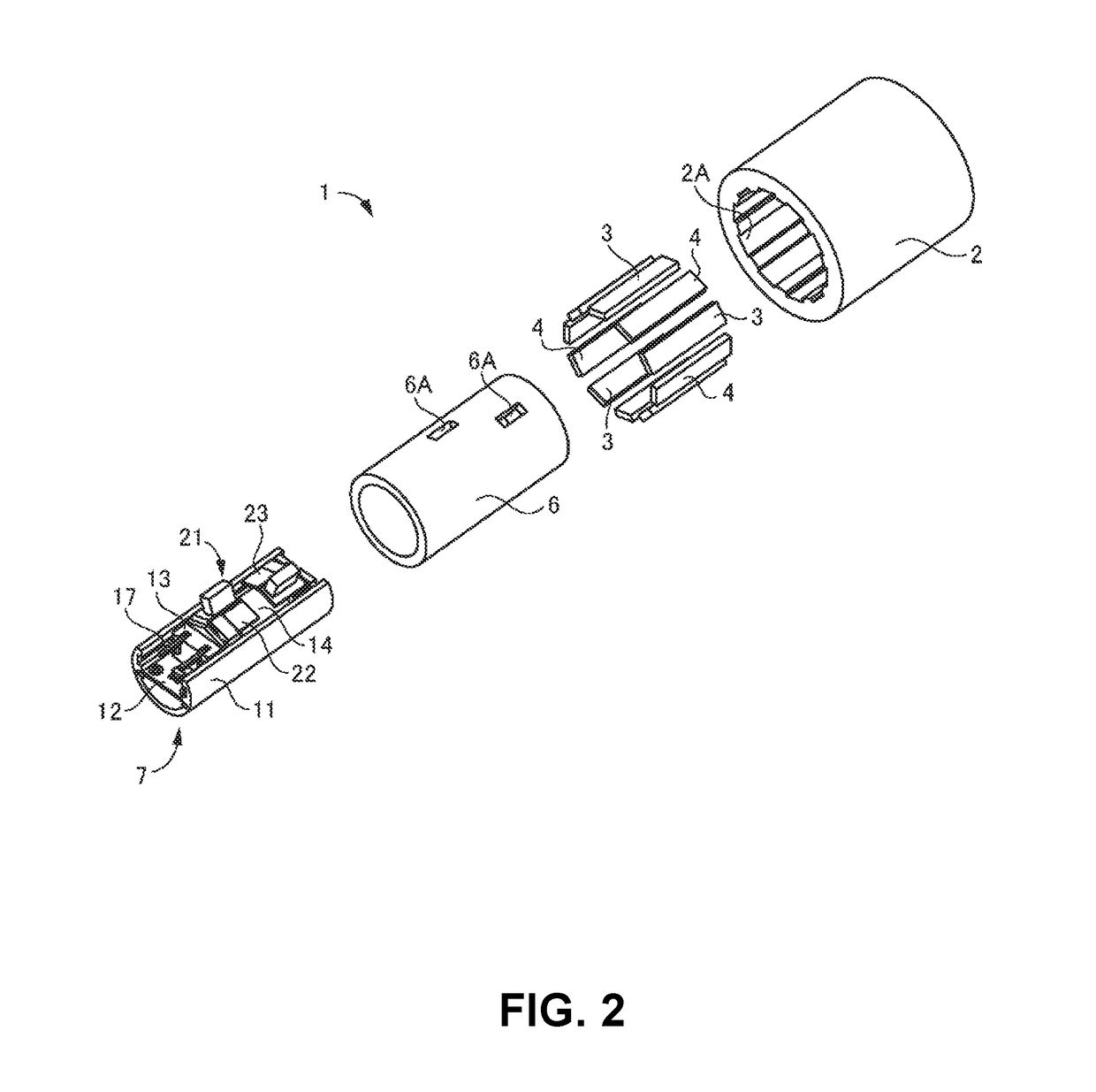
[0055]A first embodiment of the present invention will be explained. FIG. 1 is a schematic plan view showing a configuration of a rotation detecting device 1 according to the first embodiment of the present invention. FIG. 2 is a schematic exploded perspective view showing the configuration of the rotation detecting device 1 according to the first embodiment of the present invention.

[0056]As shown in FIGS. 1 and 2, the rotation detecting device 1 includes a cylindrical member (a base member) 6 and a rotational member 2 with a cylindrical shape. The rotational member 2 is inserted into the cylindrical member 6, so that the rotational member 2 is rotated around a rotational axis X thereof relative to the cylindrical member 6. A plurality of magnets 3 and a plurality of magnets 4 as magnetic field generating portions are fixed to the rotational member 2. A detection unit 7 is fixed in the cylindrical member 6, and includes a detection member 14 and a yoke 21 as a magnetic field introdu...

second embodiment

[0106]A second embodiment of the present invention will be explained next. FIG. 9 is a schematic plan view showing a configuration of a rotation detecting device 41 according to the second embodiment of the present invention. FIG. 10 is a schematic perspective view showing the configuration of the rotation detecting device 41 according to the second embodiment of the present invention.

[0107]As shown in FIGS. 9 and 10, the rotation detecting device 41 includes the detection member 14 and a yoke 45. The detection member 14 includes a plurality of magnets 42 and 43, the magnetic member 15, and the coil 16. The yoke 45 includes a pair of yoke pieces 46 and 47.

[0108]In the second embodiment, similar to the rotation detecting device 1 in the first embodiment, the magnets 42 and the magnets 43 are magnetized in a direction perpendicular to the rotational axis X of the rotational member 2. Further, the magnets 42 and the magnets 43 are arranged along the circumferential direction of the rot...

third embodiment

[0113]A third embodiment of the present invention will be explained next. FIG. 11 is a schematic plan view showing a configuration of a rotation detecting device 51 according to the third embodiment of the present invention. FIG. 12 is a schematic perspective view showing the configuration of the rotation detecting device 51 according to the third embodiment of the present invention.

[0114]As shown in FIGS. 11 and 12, the rotation detecting device 51 includes the detection member 14 and a yoke 55. The detection member 14 includes a plurality of magnets 52 and 53, the magnetic member 15, and the coil 16. The yoke 55 includes a pair of yoke pieces 56 and 57.

[0115]In the third embodiment, the magnets 52 and the magnets 53 are fixed to the rotational member 2. Different from the rotation detecting device 1 in the first embodiment, each of the magnets 52 includes a magnet piece 52A and a magnet piece 52B as a magnetic field generating piece. The magnet piece 52A and the magnet piece 52B a...


PUM


Abstract

A rotation detecting device includes a plurality of magnetic field generating portions; a magnetic member; a coil wound around the magnetic member; and a magnetic field introducing portion. The magnetic field introducing portion introduces a magnetic flux generated by the magnetic field generating portion to pass through the magnetic member when the magnetic field generating portion passes through a specific location.

Description

BACKGROUND TECHNOLOGY AND RELATED TECHNOLOGY[0001]The present invention relates to a rotation detecting device for detecting a rotation of a detection subject using a magnetic force.[0002]Patent Reference 1 has disclosed a conventional rotation detecting device. FIG. 13 is a schematic perspective view showing the conventional rotation detecting device 101 disclosed in Patent Reference.[0003]Patent Reference: Japanese Patent Publication No. 2001-194182[0004]As shown in FIG. 13, the conventional rotation detecting device 101 includes a plurality of magnets 102 and a detection element 103. Each of the magnets 102 is fixed on an outer circumference portion of a rotational member 104 having a cylindrical shape. Further, each of the magnets 102 is formed of a permanent magnet, and is magnetized in a direction in parallel to a rotational axis 105 of the rotational member 104. Further, the magnets 102 are arranged along an outer circumference direction of the rotational member 104 such that...

Claims


Application Information

Patent Timeline
IPC IPC(8): G01D5/20
CPCG01D5/2033G01P3/4815G01D2205/40G01P3/487H02P6/16G01D5/145
Inventor OYAMA, SHOJIKASUGA, ATSUSHI
Owner HIROSE ELECTRIC GROUP
Why Eureka
Try Eureka