
Single-shot hyperspectral wavefront sensor

Pending Publication Date: 2022-06-09
UNIVERSITÉ PARIS CITÉ +4
View PDF0 Cites 0 Cited by
  • Summary
  • Abstract
  • Description
  • Claims
  • Application Information

AI Technical Summary

Benefits of technology

The invention is a method for measuring the wavefront shapes of a multi-spectral light beam using a single image acquisition from a same multi-spectral light beam. This method uses an optical assembly made of an optical mask and an imaging sensor. The optical mask has properties that cause the intensity pattern of the light beam to depend on the wavefront shape, and the imaging sensor records the intensity patterns of incident beams. The method involves recording reference intensity patterns for each wavelength and computing intensity-weight data and deformation data for each reference intensity pattern. The deformation data is then used to generate data for each wavelength that represents the shape of the wavefront. This allows for simultaneous measurement of wavefront shapes at different wavelengths, which is useful in various applications such as optical metrology and ophthalmology.

Problems solved by technology

However, if the light beam is composed of several beams originating from different sources emitting at different wavelengths, each of which exhibiting a different wavefront, all these wavefronts cannot be reconstructed simultaneously.
The reconstruction algorithm will converge towards a solution but this result is physically meaningless.
However, high-power, ultrashort lasers usually have low repetition rates, as low as a few pulses per day.
Moreover, the current technical solution has several drawbacks: i) it is complicated, ii) it is expensive since it requires many filters with very sharp spectral properties, iii) it takes time as spectral measurements are made sequentially, and it is therefore not applicable to quickly evolving systems.

Method used


Image

  • Single-shot hyperspectral wavefront sensor
  • Single-shot hyperspectral wavefront sensor
  • Single-shot hyperspectral wavefront sensor

Examples


Embodiment Construction

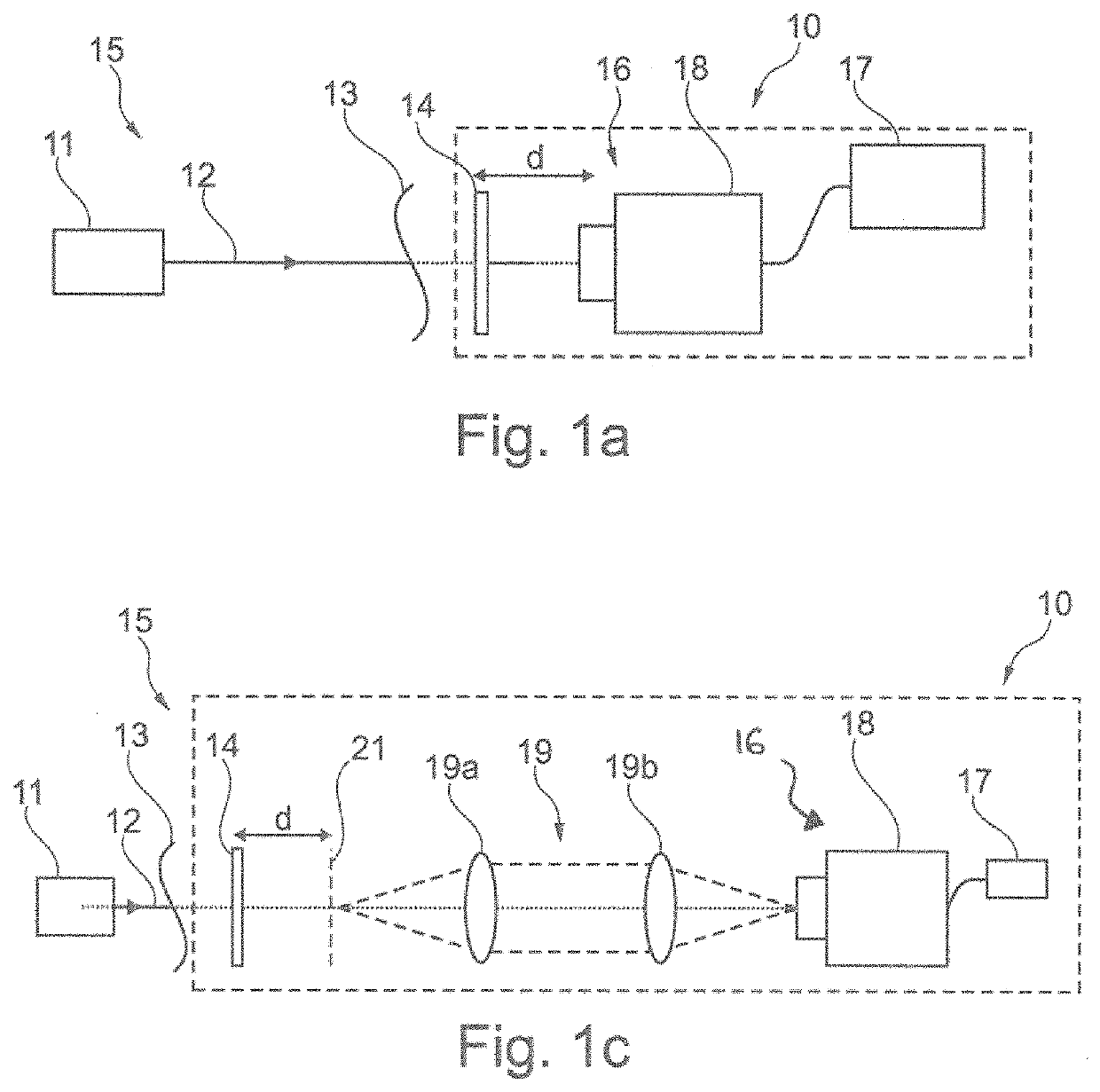
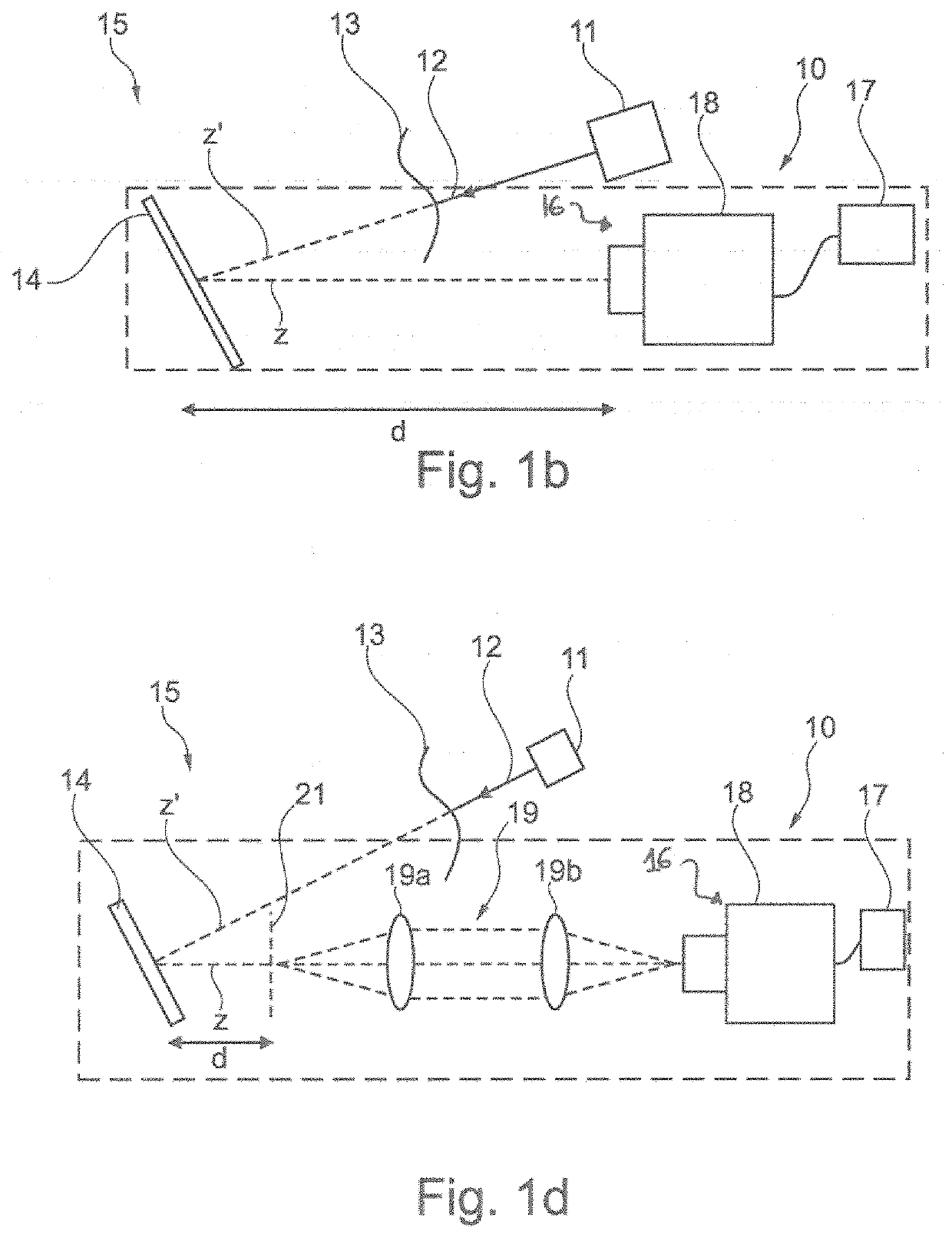
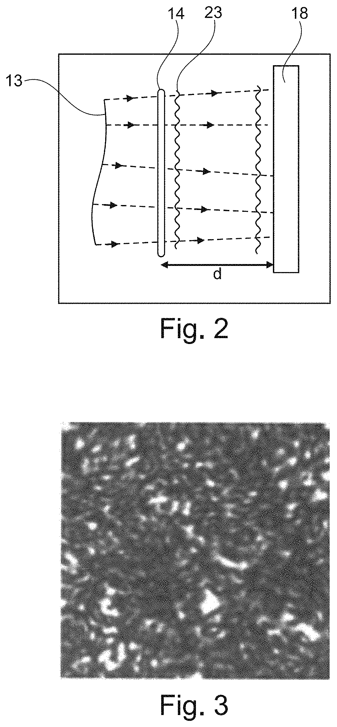
[0198]In an embodiment, a method according to the present invention relies on the specific properties of random intensity patterns generated by diffusers or more generally by an optical mask having the optical properties:

[0199]i) to cause the intensity pattern to depend on the wavefront shape, so that a tilt applied to the wavefront shape results in a displacement amount of the intensity pattern,

[0200]ii) to produce uncorrelated intensity patterns over at least one surface area A of the imaging sensor, for a plurality of respective incident monochromatic beams of different wavelengths having a same wavefront shape,

[0201]The principle is described below.

[0202]If two beams exhibit the same wavefront and the same intensity distribution, and only differ in their wavelength, the intensity patterns on the camera will be different. The similarity degree between two intensity patterns{sj}j=1,2, obtained at two different wavelengths depends on the spectral difference δA=λ1−λ2.

[0203]The degre...


PUM


Abstract

A method for determining wavefront shapes of a multi-spectral signal light beam from a single signal image acquisition of said multi-spectral signal beam, with a device including an optical assembly made at least of an optical mask and an imaging sensor, notably a matrix imaging sensor, for generating and recording intensity patterns of incident beams, by having these beams reflect on, or propagate through, the optical mask. The optical mask having the optical properties: i) to cause the intensity pattern to depend on the wavefront shape, so that a tilt applied to the wavefront shape results in a displacement amount of the intensity pattern, and ii) to produce uncorrelated intensity patterns over at least one surface area A of the imaging sensor, for a plurality of respective incident monochrome beams of different wavelengths having a same wavefront shape.

Description

[0001]The present invention relates to an optical system for laser beam characterization, quantitative phase imaging and other applications.DESCRIPTION OF THE RELATED ART[0002]Wavefront sensors, referred to as WFS in the following, are used to measure the wavefront of a light beam, defined as its curvature relative to a planar wavefront shape. They find applications in several domains ranging from laser beam metrology to quantitative phase imaging of biological objects and astronomy.[0003]A WFS is typically composed of a phase or intensity mask placed before an intensity detector, a camera for example. The mask is used to create an intensity pattern on the camera. First, a reference beam is sent onto the WFS, with a planar wavefront or any other a priori known reference wavefront to measure a reference intensity pattern. Next, a signal beam is sent onto the WFS and generates a signal intensity pattern. The intensity pattern changes due to the wavefront change, even in the absence of...

Claims


Application Information

Patent Timeline
IPC IPC(8): G01J9/00
CPCG01J9/00
Inventor GUILLON, MARCBERTO, PASCALPAPADOPOULOS, DIMITRISTESSIER, GILLES
Owner UNIVERSITÉ PARIS CITÉ
Learn More