
Printing Apparatus

Active Publication Date: 2018-10-04
BROTHER KOGYO KK
View PDF1 Cites 0 Cited by
  • Summary
  • Abstract
  • Description
  • Claims
  • Application Information

AI Technical Summary

Benefits of technology

The present invention provides a printing apparatus with high accuracy in correcting the amount of energy to be applied. By using two temperature sensors, one inside the main body and one near the thermal head, the apparatus can accurately measure the temperature and adjust the amount of energy accordingly. This results in minimized deviation between the temperature changes and the ink ribbon, allowing for precise and accurate printing.

Problems solved by technology

In a printing apparatus of this type, in a case where an amount of energy (hereinafter, referred to as “applying energy”) to be applied to the heating element is excessively small, there is a possibility that characters printed are faint and patchy.
In a case where the amount of applying energy is excessively large, there is a possibility that the characters printed are blurred.
In such manner, in a case where the amount of applying energy is inappropriate, there is a possibility that there arises a printing defect.
Practically, it is difficult to detect directly the temperature of the printing medium which is conveyed during printing.
In this case, there arises deviation between change in the temperature detected by the ambient temperature sensor and change in the temperature of the printing medium, and there is a possibility that an accuracy of correcting the amount of applying energy is degraded.

Method used


Image

  • Printing Apparatus
  • Printing Apparatus
  • Printing Apparatus

Examples


Embodiment Construction

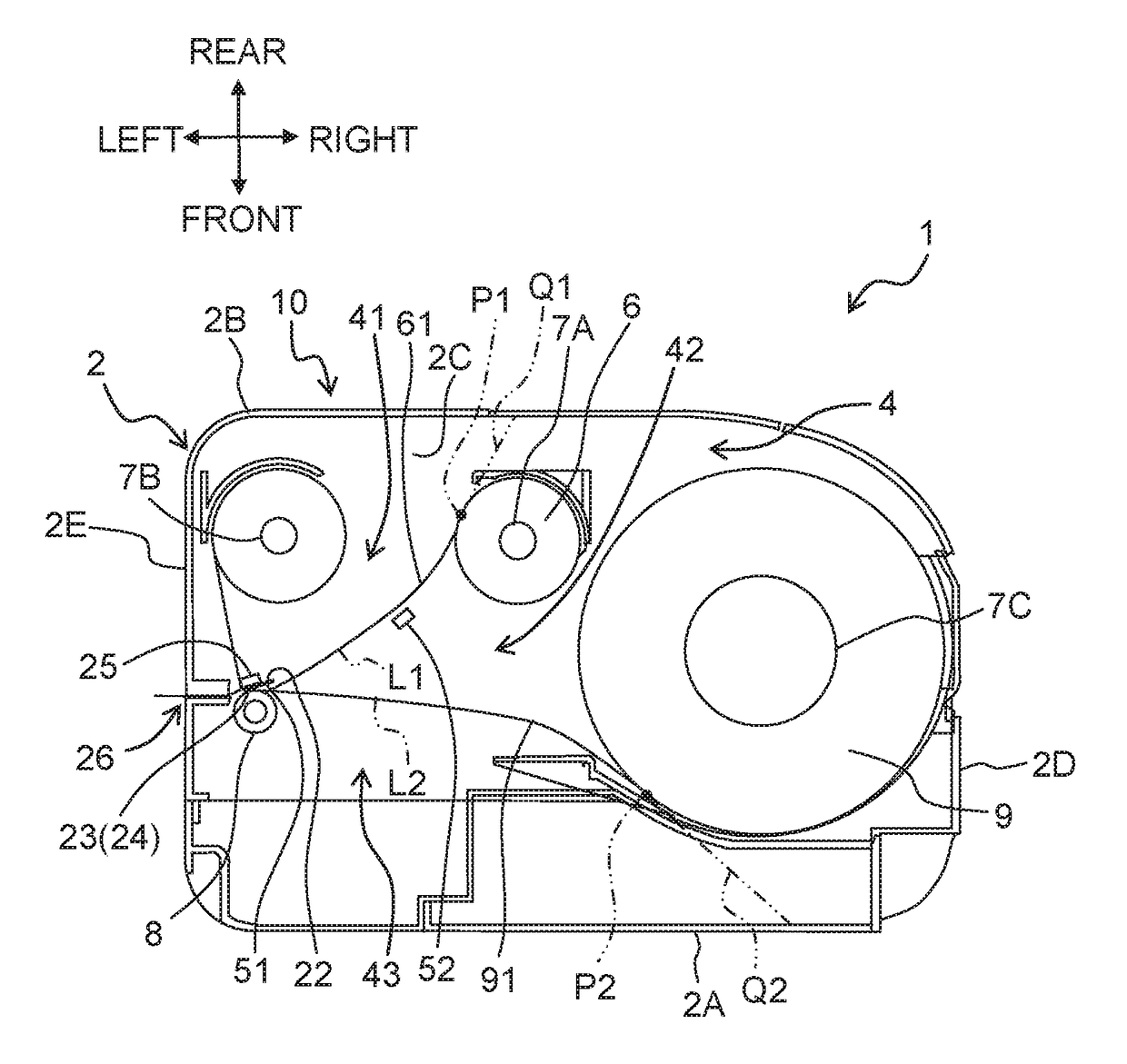
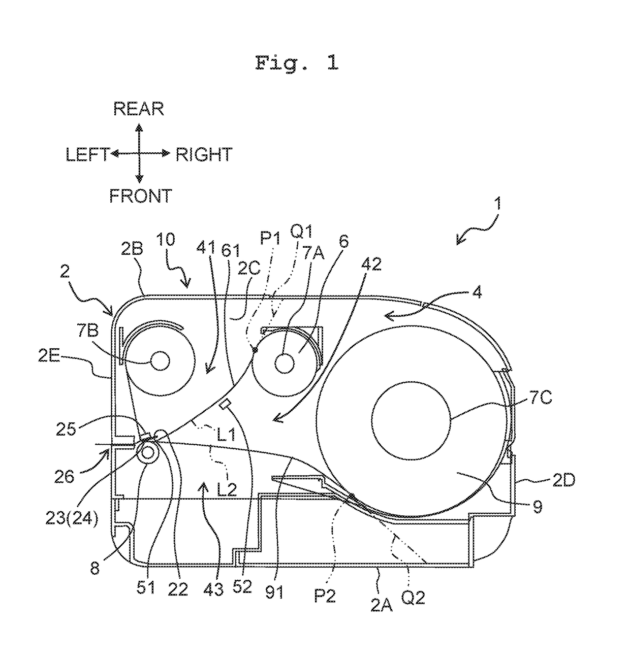
[0012]An embodiment of the present teaching will be described below by referring to the accompanying diagrams. A printing apparatus 1 is connectable to an external terminal (omitted in the diagram) via a USB (universal serial bus) (registered trademark) cable. The printing apparatus 1 is capable of printing alphabets and characters such as figures (graphic characters) on a printing object via an ink ribbon 61, on the basis of print data received from the external terminal. The external terminal is a general purpose personal computer (PC). The printing object is a printing tape 91. The printing apparatus 1 can be driven by a battery. A left side, a right side, an upper side, a lower side, a front side of a paper surface, and rear side of a paper surface in FIG. 1 will be defined as a left side, a right side, a rear side, a front side, an upper side, and a lower side respectively, of the printing apparatus 1.

[0013]A mechanical arrangement of the printing apparatus 1 will be described ...


PUM


Abstract

A printing apparatus includes: a main body having a space therein, a thermal head arranged on a substrate provided in the space, the thermal head having heating elements arranged along a predetermined arrangement direction; a first conveyor which conveys an ink ribbon along a first conveyance path orthogonal to the arrangement direction, a second conveyor which conveys a printing object along a second conveyance path orthogonal to the arrangement direction and on an opposite side of the thermal head with respect to the first conveyance path, a first temperature sensor provided in a first space on a side of the thermal head with respect to the first conveyance path, a second temperature sensor provided in a second space between the first conveyance path and the second conveyance path, and a processor.

Description

CROSS REFERENCE TO RELATED APPLICATION[0001]The present application claims priority from Japanese Patent Application No. 2017-067072 filed on Mar. 30, 2017, the disclosure of which is incorporated herein by reference in its entirety.BACKGROUNDField of the Invention[0002]The present invention relates to a printing apparatus.Description of the Related Art[0003]A printing apparatus in which an energy is applied to a heating element of a thermal head, and printing is carried out by imparting heat to a printing medium by the heating element that has generated heat has been known (For example, Japanese Patent Application Laid-open No. 2001-315374). In a printing apparatus of this type, in a case where an amount of energy (hereinafter, referred to as “applying energy”) to be applied to the heating element is excessively small, there is a possibility that characters printed are faint and patchy. In a case where the amount of applying energy is excessively large, there is a possibility that ...

Claims


Application Information

Patent Timeline
IPC IPC(8): B41J2/365B41J33/02B41J2/325
CPCB41J2/365B41J33/02B41J2/325B41J2202/31B41J2/04563B41J3/4075
Inventor KONDO, TOMOHIROTORII, YASUHIROTERADA, KOHEI
Owner BROTHER KOGYO KK
Learn More