Image Forming Apparatus, Image Forming Method and Storage Medium

a technology of image forming and forming method, which is applied in the direction of electrographic process apparatus, instruments, optics, etc., can solve the problems of difficult removal of the remaining toner on the image carrying member, and increased development costs, so as to prevent the wear of the clearing unit and increase the developer consumption amount

Active Publication Date: 2017-05-04
KONICA MINOLTA INC
View PDF4 Cites 6 Cited by
  • Summary
  • Abstract
  • Description
  • Claims
  • Application Information

AI Technical Summary

Benefits of technology

[0012]Objects of the present invention include providing an image forming apparatus, an image forming method and a storage medium each of which can more certainly prevent wear of a clearing unit without increasing the developer consumption amount.

Problems solved by technology

This makes removal of the remaining toner on the image carrying member difficult.
That is, poor cleaning, called “passing through”, tends to occur.
This makes removal of the remaining toner on the image carrying member more difficult.
Further, when the toner particles passing through the blade exist, aggregations of the toner particles having the toner particles as nuclei are formed on the image carrying member, and thereby particle-shaped voids (particle-shaped noise) are generated in the region of a solid image formed on paper.
At a low dot percentage part in an image on the image carrying member, the toner particles and the external additive reaching the cleaning blade are a little, and hence the amount of the toner particles and the external additive accumulating at the tip of the blade is insufficient, whereby power to scrape away and collect the lubricant on the image carrying member decreases.
However, when the lubricant amount is too much, another problem arises that the cleaning blade and the image carrying member come in close contact, which facilitates wear of the cleaning blade and thereby shortens life thereof.
Hence, the amount of the toner particles and the external additive accumulating at the tip of the cleaning blade is insufficient, which cannot reduce the lubricant amount on the low dot percentage part on the image carrying member and cannot prevent wear of the cleaning blade from progressing.
However, if, then, the developer supply amount for a patch is set at a value which can reduce the lubricant amount on the low dot percentage part when an image having a high overall coverage is continuously printed, the developer supply amount is too much when an image having a low overall coverage is printed, which increases the developer consumption amount.

Method used


Image

  • Image Forming Apparatus, Image Forming Method and Storage Medium
  • Image Forming Apparatus, Image Forming Method and Storage Medium
  • Image Forming Apparatus, Image Forming Method and Storage Medium

Examples


examples

[0120]Hereinafter, the present invention is described with Examples. However, the present invention is not limited thereto.

first example

101>>

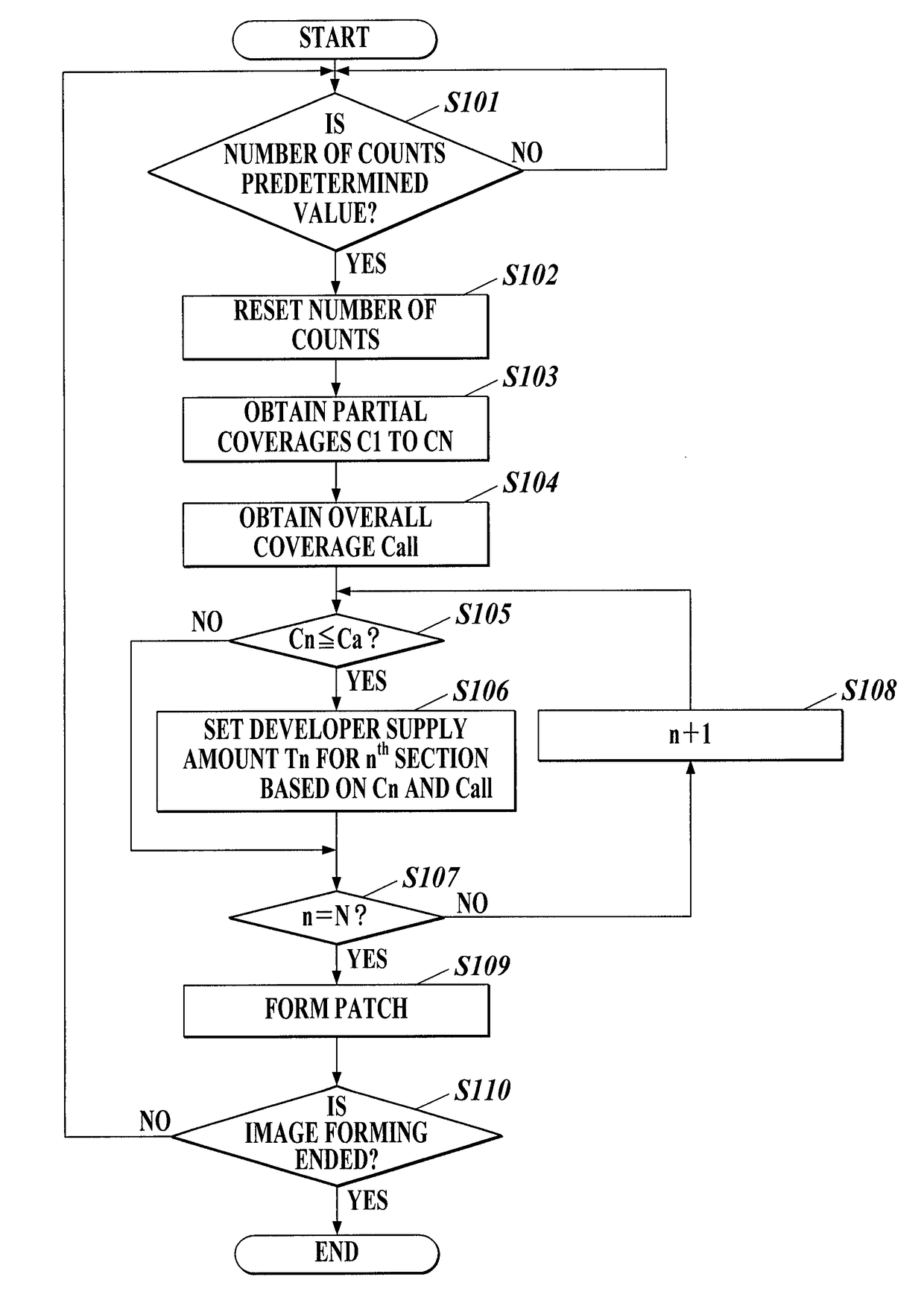
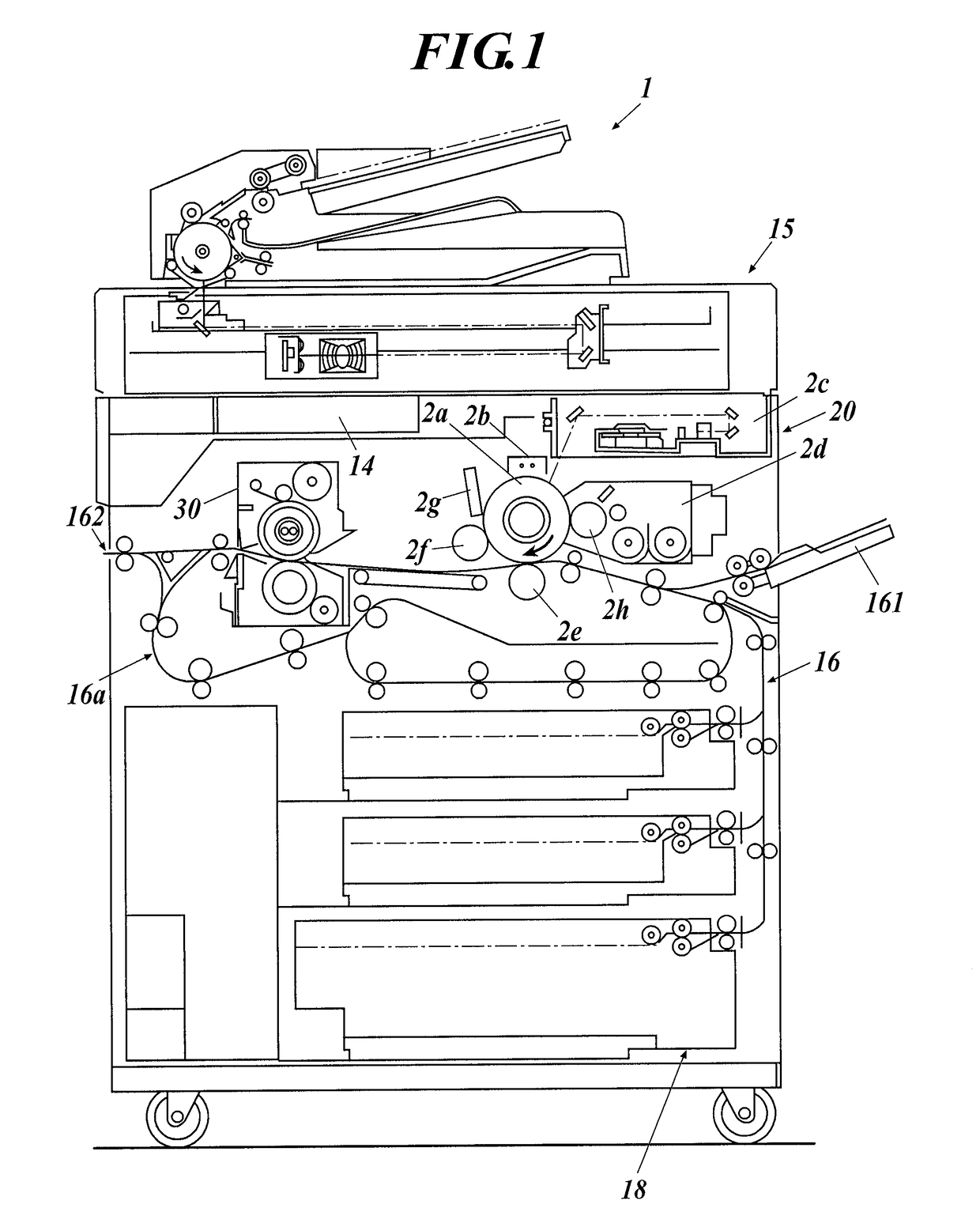
[0121]Prepared was an image forming apparatus 101 having almost the same configuration as the image forming apparatus 1 shown in FIG. 1, wherein the control unit 11 was configured to form no patch.

102>>

[0122]Prepared was an image forming apparatus 102 having almost the same configuration as the image forming apparatus 1 shown in FIG. 1, wherein the control unit 11 was configured to form a patch of a horizontally long belt-shaped solid pattern having a dot percentage corresponding to a coverage of 5% between image forming regions with respect to the nth section having the partial coverage Cn=0(%) among 12 sections into which the surface of the photoreceptor 2a is divided in the rotating shaft direction of the photoreceptor 2a.

103>>

[0123]Prepared was an image forming apparatus 103 having almost the same configuration as the image forming apparatus 1 shown in FIG. 1, wherein the control unit 11 was configured to form a patch of a horizontally long belt-shaped solid pattern having...

second example

201>>

[0142]Prepared was an image forming apparatus 201 having the same configuration as the image forming apparatus 104 in First Example.

202>>

[0143]The image forming apparatus 1 shown in FIG. 1 was configured as follows, thereby being prepared as an image forming apparatus 202.

[0144]That is, the control unit 11 was configured to form a patch of a horizontally long belt-shaped solid pattern having a dot percentage set based on the partial coverage Cn and the overall coverage Call, as shown in TABLE 3 below, between image forming regions with respect to each of 12 sections into which the surface of the photoreceptor 2a is divided in the rotating shaft direction of the photoreceptor 2a.

TABLE 3Call = 10Call = 25Call = 7010.0 ≦ Cn 0% 0% 0% 5.0  0% 0%2.0%3.5 0.3%0.7%4.0%2.0 0.5%1.5%5.0% 0 ≦ Cn ≦ 2.02.0%3.0%7.0%

201 and 202>>

[0145]Using each of the above image forming apparatuses 201 and 202, vertically long belt-shaped charts respectively having overall coverages Call of 10%, 25% and 70% w...


PUM


Abstract

An image forming apparatus includes an image carrying member, a developing device, a cleaning unit and a processor. The developing device performs development with a developer containing a toner and a lubricant. The processor obtains information on a lubricant amount in the developing device; obtains, with respect to each section formed by dividing a surface of the image carrying member in a rotating shaft direction of the image carrying member, a partial coverage from electrostatic latent image writing information for a predetermined period about the section; sets, for the section having the partial coverage of a predetermined value or less, a developer supply amount for a patch to be formed outside an image forming region on the image carrying member, based on the above information; and causes the developing device to supply the set developer supply amount so that the patch is formed.

Description

CROSS-REFERENCE TO RELATED APPLICATIONS[0001]This application claims a priority under the Paris Convention of Japanese Patent Application No. 2015-216254 filed on Nov. 4, 2015, the entire disclosure of which, including the specification, claims, drawings and abstract, is incorporated herein by reference in its entirety.1. FIELD OF THE INVENTION[0002]The present invention relates to an image forming apparatus, an image forming method and a storage medium.2. DESCRIPTION OF THE RELATED ART[0003]There has been provided an electrophotographic image forming apparatus having a cleaning unit which removes the remaining toner on an image carrying member, such as non-transferred toner or toner left after the transfer. As the cleaning unit, for example, there has been known one employing a blade cleaning system, namely, a flat cleaning blade made of an elastic substance and removing the remaining toner on the image carrying member by pressing in contact with the surface of the image carrying m...

Claims


Application Information

Patent Timeline
Patent Type & Authority Applications(United States)
IPC IPC(8): G03G15/08G03G15/00G03G15/16
CPCG03G15/50G03G21/0005G03G21/0094G03G15/6585G03G15/5058G03G15/5041G03G15/556
Inventor SATO, YUYAHIRAI, ATSUTO
Owner KONICA MINOLTA INC
Why Eureka
Try Eureka