
Touch display apparatus and shift register thereof

a technology of display apparatus and shift register, which is applied in the direction of digital storage, instruments, computing, etc., can solve the problems of component performance deterioration, display quality degradation, mura effect,

Active Publication Date: 2017-05-04
AU OPTRONICS CORP
View PDF0 Cites 39 Cited by
  • Summary
  • Abstract
  • Description
  • Claims
  • Application Information

AI Technical Summary

Benefits of technology

The present invention provides a shift register with multi-stage shift circuits for outputting a plurality of scan signals. The shift register circuits include a driving unit, a pull-up unit, a pull-down unit, a pull-down control unit, a reset unit, and an electric storage unit. The shift register circuits are controlled by a first clock signal and a second clock signal, which are phase-inverted periodic signals. The electric storage unit includes a first switch, a second switch, and a first capacitor. The invention also provides a sensing display apparatus and a driving method for the shift register. The technical effects of the invention include improved accuracy and reliability in outputting scan signals and sensing signals, as well as improved responsiveness and stability of the display panel.

Problems solved by technology

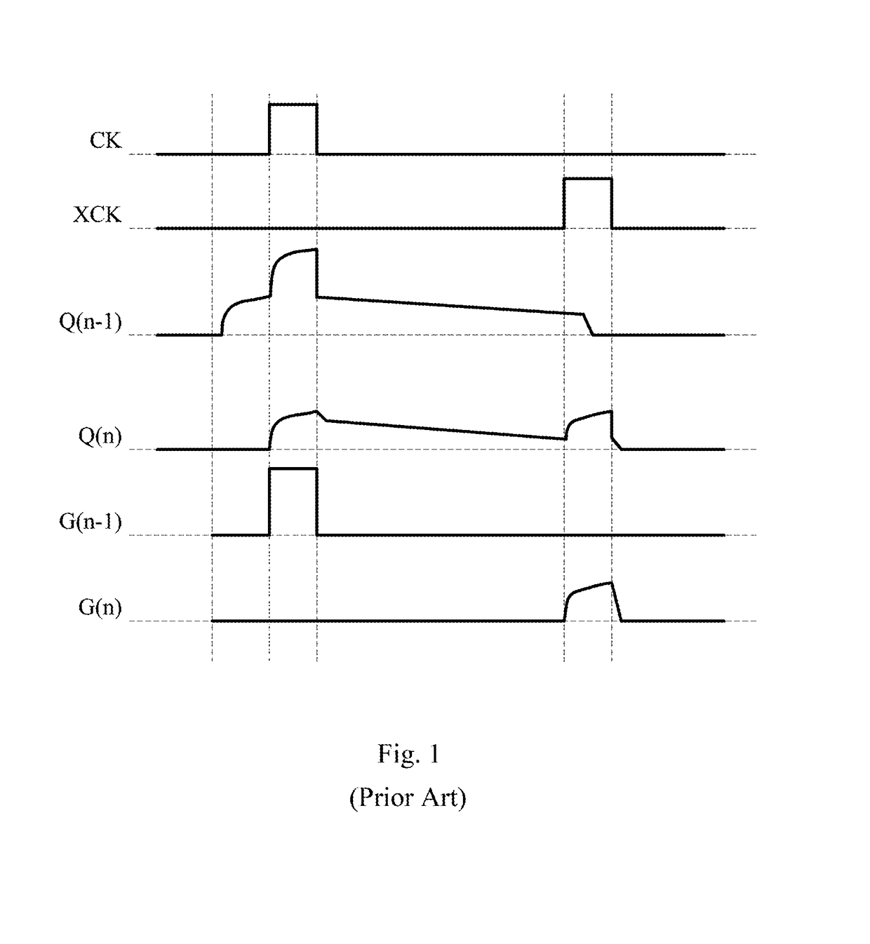
When the display driving is restored, the scan signal G(n−1) has leakage due to the floating of the internal driving node of the display driving circuit in the display-pause period, causing failure of the scan signal G(n) after the display-pause period to output a correct voltage level, thereby degrading the display quality.
In addition, the waveform distortion of the restored scan signal G(n) results in inconsistency between the time of a falling edge in the waveform and the time of a falling edge of scan signals from other stages, causing the mura effect.
Thus, how to prevent the driving transistor of the shift register circuits from being stressed for a long time, resulting in component performance deterioration and thus erroneous output is one of the important development issues today, and also has become an object urgently in need of improvement in related fields today.

Method used


Image

  • Touch display apparatus and shift register thereof
  • Touch display apparatus and shift register thereof
  • Touch display apparatus and shift register thereof

Examples


Embodiment Construction

[0016]Embodiments will be described below in detail in conjunction with the accompanying drawings, but the embodiments are not intended to limit the scope of the present invention. The order in which the operations of a structure are described is not to be construed as a limitation, and any structure which is a rearrangement of the components, and the resulting apparatus having an equivalent effect all fall within the scope of the present invention. In addition, the figures are merely illustrative and have not been drawn to scale. To facilitate understanding, same elements in the following description are labeled by the same reference numerals.

[0017]The terms “first”, “second” and the like used herein do not denote any particular order or sequence, are not intended to limit the present invention, and are used only for distinguishing between elements or operations described with same technical terms.

[0018]Additionally, the terms “coupled” and “connected” used herein may mean that two...


PUM


Abstract

A shift register circuit includes a driving unit outputting a first scan signal according to a first clock signal; a pull up unit outputting a driving voltage according to one of a second scan signal and a third scan signal; a pull down unit pulling down voltage of an output end according to a second clock signal; a pull down control unit controlling the voltage of the output end and a driving node according to the first clock signal; a reset unit pulling down the voltage level of the driving node according to a touch-enable signal; and an electric storage unit adjusting the voltage of the driving node according to a touch-stop signal. When the touch-enable signal is enabled, the clock signals and the touch-stop signal are disabled, and when the touch-stop signal is enabled, the clock signals and the touch-enable signal are disabled.

Description

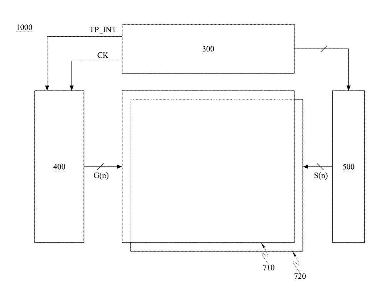
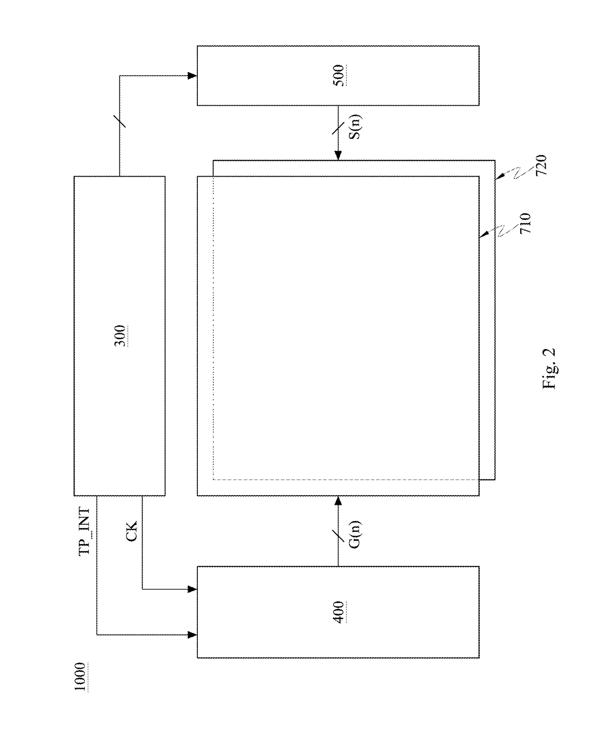
TECHNICAL FIELD[0001]The present invention generally relates to a display scan driver, and in particular, to a display scan driver suitable for a display having a touch function.BACKGROUND[0002]Recently, various LCD products have become popular for use in mobile hand-held devices. In addition, due to widespread use of smart end devices, integration of a touch function into smart end devices has become a mainstream demand for current products.[0003]Referring to FIG. 1, a conventional touch display apparatus having a touch display function initiates a touch driver in a display-pause period for touch driving. As shown, FIG. 1 is a waveform schematic diagram of a conventional shift register having a touch display function, where a display panel has a plurality of scan lines, and a scan driver comprising multi-stage shift register circuits, a clock signal CK, scan signals G(n−1), G(n), and driving voltages Q(n−1), Q(n). In each frame period, the shift register circuits output the scan si...

Claims


Application Information

Patent Timeline
Patent Type & Authority Applications(United States)
IPC IPC(8): G06F3/041G09G3/36G11C19/28G06F3/044
CPCG06F3/0416G06F3/044G06F3/0412G09G2310/0286G09G3/3696G11C19/28G09G2300/0842G09G3/3677G06F3/04184G09G3/20G09G2310/0267
Inventor LIN, CHIH-LUNGLAI, PO-CHUNWU, CHIA-ENKO, CHIEN-CHUANTSAI, MENG-CHIEH
Owner AU OPTRONICS CORP
Learn More