Methods and systems for communication with beamforming antennas

a beamforming antenna and communication method technology, applied in the direction of radio transmission, electrical equipment, assess restriction, etc., can solve the problems of preventing similar antenna systems from operating simultaneously at the same frequency, high energy cost per bit transmitted, expensive and bulky, etc., to increase network capacity, reduce power consumption, and increase data rate

Active Publication Date: 2017-05-04
DE INVENSHN SAJENS FAND UAN ELELSI
View PDF4 Cites 87 Cited by
  • Summary
  • Abstract
  • Description
  • Claims
  • Application Information

AI Technical Summary

Benefits of technology

[0003]Commercialized, low C-SWAP (Cost, Size, Weight and Power), software defined communications apertures will substantially increase network capacity in future wireless networks (e.g., 5G wireless networks). Embodiments of the present invention provide methods and systems that employ high gain, electronically steerable antennas for small cell radio access networks, backhaul, and millimeter wave applications. The steerable beam functionality may provide elevated data rates, reduced power consumption, spectrum reuse, and dynamic network reconfiguration. Additionally, network operating costs may be reduced and deployment schedules may become more flexible.

Problems solved by technology

Using low directivity antennas fundamentally leads to a higher energy cost per bit transmitted as the overwhelming majority of the radiated power is not captured by the receiving antenna unit.
In addition, low directivity antennas spectrally pollute their coverage area, preventing similar antenna systems from operating simultaneously at the same frequency.
However, a substantial number of fixed antennas would be needed to assure coverage, which would be expensive and bulky.
However, they are likely to be far too slow, bulky and expensive to address multiple users within the coverage area adequately.
The small cells are unlikely to have dedicated fiber or wired links due to the predicted density of their deployment.

Method used


Image

  • Methods and systems for communication with beamforming antennas
  • Methods and systems for communication with beamforming antennas
  • Methods and systems for communication with beamforming antennas

Examples


Embodiment Construction

[0031]In the following detailed description, reference is made to the accompanying drawings, which form a part hereof. In the drawings, similar symbols typically identify similar components, unless context dictates otherwise. The illustrative embodiments described in the detailed description, drawings, and claims are not meant to be limiting. Other embodiments may be utilized, and other changes may be made, without departing from the spirit or scope of the subject matter presented here.

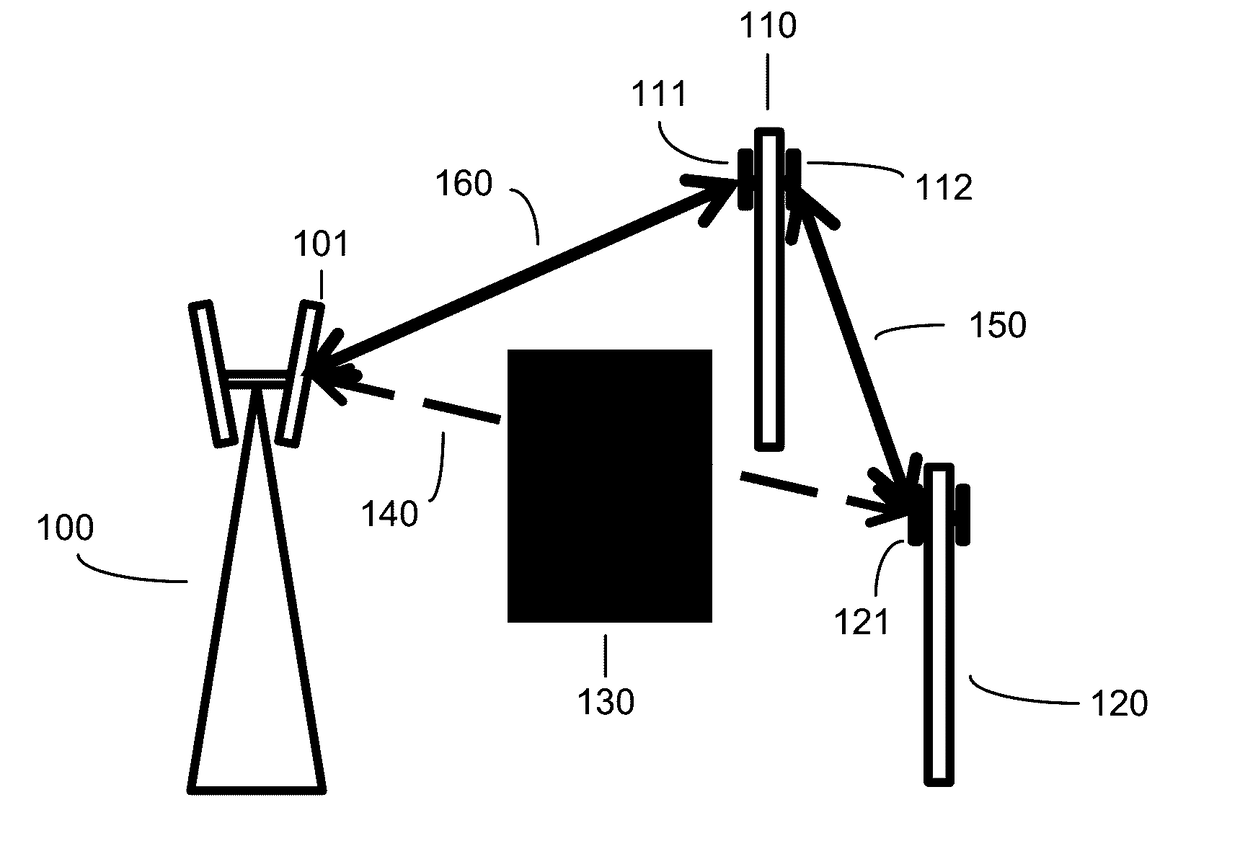
[0032]With reference to FIG. 1A, an illustrative scenario is depicted for adaptive routing within a communications network. The illustrative network includes three nodes 100, 110, and 120. The node 100 is depicted as a macro cell node and the nodes 110 and 120 are depicted as small cell nodes, but this depiction is not intended to be limiting; in various embodiments, each of the various nodes can be selected from a list of node types that includes macro cell nodes, small cell nodes (including nano, pi...


PUM


Abstract

Holographic beamforming antennas may be utilized for adaptive routing within communications networks, such as wireless backhaul networks. Holographic beamforming antennas may be further utilized for discovering and / or addressing nodes in a communication network with steerable, high-directivity beams. Holographic beamforming antennas may be further utilized for extending the range of communications nodes and providing bandwidth assistance to adjacent nodes via dynamic adjacent cell assist. In some approaches, MIMO is used in concert with holographic beamforming for additional channel capacity.

Description

CROSS-REFERENCE TO RELATED APPLICATIONS[0001]The present application claims benefit of priority of U.S. Provisional Patent Application No. 62 / 175,933, entitled DYNAMIC ADJACENT CELL ASSIST FOR WIRELESS COMMUNICATIONS AND ADAPTIVE NETWORK CELLULAR BACKHAUL, naming ERIC BLACK, BRIAN DEUTSCH, ALEXANDER KATKO, MELROY MACHADO, JAY MCCANDLESS, AND YAROSLAV URZHUMOV as inventors, filed Jun. 15, 2015, which was filed within the twelve months preceding the filing date of the present application.[0002]All subject matter of all of the above applications is incorporated herein by reference to the extent such subject matter is not inconsistent herewith.BACKGROUND AND SUMMARY[0003]Commercialized, low C-SWAP (Cost, Size, Weight and Power), software defined communications apertures will substantially increase network capacity in future wireless networks (e.g., 5G wireless networks). Embodiments of the present invention provide methods and systems that employ high gain, electronically steerable ante...

Claims


Application Information

Patent Timeline
Patent Type & Authority Applications(United States)
IPC IPC(8): H04W16/28H04W48/16H04B7/0413
CPCH04W16/28H04B7/0413H04W48/16H04B7/0617H04B7/0695H04W16/06H04W24/10
Inventor BLACK, ERIC J.DEUTSCH, BRIAN MARKHANNIGAN, RUSSELL J.KATKO, ALEXANDER REMLEYMACHADO, MELROYMCCANDLESS, JAY HOWARDURZHUMOV, YAROSLAV A.
Owner DE INVENSHN SAJENS FAND UAN ELELSI
Why Eureka
Try Eureka