
System and method for determining corrective vision

a technology of corrective vision and system, applied in the field of contact lenses, can solve the problems of low prevalence of patients needing higher power correction, high cost of tool and mold manufacturing, and high cost of casting molding for a large number of skus

Active Publication Date: 2017-05-11
JOHNSON & JOHNSON VISION CARE INC
View PDF5 Cites 7 Cited by
  • Summary
  • Abstract
  • Description
  • Claims
  • Application Information

AI Technical Summary

Benefits of technology

The patent describes a method for fitting a patient with refractive eyewear that can adjust the sphere power of the lenses to correct refractive errors. The method involves using software and a controller to adjust the lenses until the patient can see an image clearly. The refractive eyewear is then selected for the patient, and they are instructed to wear them for an objective examination to obtain additional data on the refractive errors. The second spherical eye refraction is then performed while the patient is wearing the fitting lenses. The technical effect of this patent is to provide a more accurate and precise method for fitting patients with refractive eyewear.

Problems solved by technology

The reasons for manufacturers only offering discrete steps in contact lens parameters are many, but may include the cost of tool and mold manufacture, inventory costs for storing large numbers of stock keeping units (SKUs) of the tools, inventory costs of storing huge quantities of lenses, the low prevalence of patients needing higher degrees of power correction, etc.
In a cost range of $100-$500 per metal tool, cast molding for a large number of SKUs is a very expensive proposition, especially when multi-cavity technology is used wherein multiple tools of the same design are used in each mold block.
This, of course, means that individuals whose prescriptions fall between or outside those ranges offered by manufacturers must purchase lenses that are less than optimal in correcting their particular vision or fit needs.
Zeroing in on an accurate corrective need for a patient using a phoropter is a time consuming process, with at each step the practitioner having to use judgment to select the next proposed lens and manually do so, and the patient having to compare one selection to the other and provide feedback to the practitioner.
With three independent variables, focus error, cylindrical power and cylindrical axis, time constraints may limit the accuracy of the end result.
Human error, both that of the patient and the practitioner, are necessarily present.
Further, subjective determination of cylindrical axis is difficult because slight differences can have a large impact on cylindrical correction.
Further, as indicated, the accuracy of a determined corrective need is limited by the resolution of the phoropter used.
Objective exams, however, do not take into account how the brain perceives and analyzes the images presented to it by the ocular system and, therefore, do not always provide the best prescriptive data for all patients.
Although this method does describe leveraging a combination of objective and subjective data, it is still plagued by the disadvantages of the phoropter described above, most notably the time consuming process, involvement of the practitioner in the process, and patient difficulty in choosing at each steps which of two options is better when lenses are flipped back and forth before them.

Method used


Image

  • System and method for determining corrective vision
  • System and method for determining corrective vision
  • System and method for determining corrective vision

Examples


Embodiment Construction

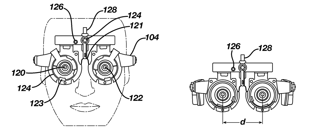
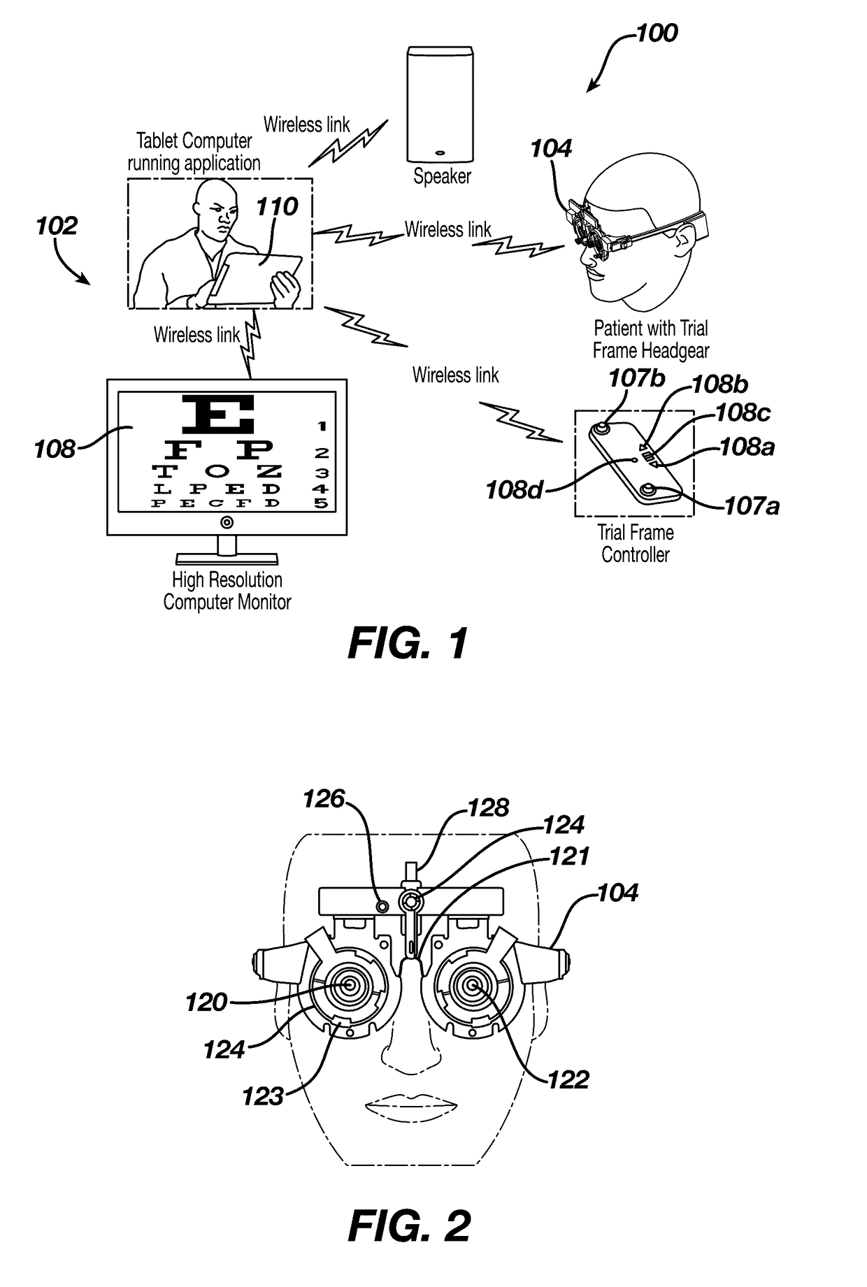
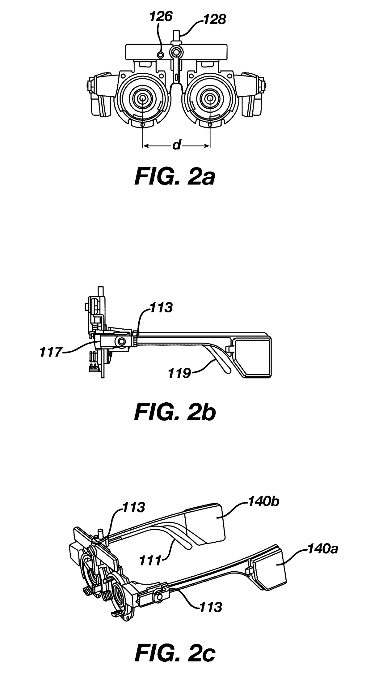
[0041]Referring now to FIG. 1, a preferred embodiment of a system for assessing optical corrective needs of a patient 100 includes a computer system 102 including computer 110 such as a tablet, laptop or desktop having a refraction software application loaded thereon, a high resolution display 108 such as a computer monitor, refractive eyewear 104 to be worn by the patient, and an eyewear controller 106 that adjusts at least sphere power in the refractive eyewear 104 lenses. In the illustrated embodiment, the computer 110 is wirelessly connected to the display device 108, and runs the refractive software application that controls the display presented to the patient. The computer 110 is further wirelessly connected, such as by a Bluetooth Low Energy communication link, to the refractive eyewear 104, and similarly to the eyewear controller 106. Although the described embodiment is preferred, those skilled in the art will readily understand that any suitable computer system can be imp...


PUM


Abstract

A system and method for assessing optical corrective needs of a patient. The system includes a computer system including a processor adapted to run at least a refractive software application thereon, an input device in communication with said processor and adapted to receive input from a user, and a displace device in communication with said processor and adapted to display information, and refractive eyewear including electrically adjustable left and right lenses selectively controllable to adjust at least a sphere power of the respective lenses and in communication with the processor. The refractive software application receives input from the input device and the eyewear controller, and selectively adjusts the sphere power of the left and right lenses, controls information displayed on said display device, and stores information regarding the sphere power of the respective left and right lenses.

Description

CROSS-REFERENCE TO RELATED APPLICATIONS[0001]This application claims priority to U.S. Provisional Application No. 62 / 198,656 (filed on Jul. 29, 2015), the contents of which are incorporated by reference in their entirety.FIELD OF THE INVENTION[0002]The present invention relates generally to the field of contact lenses, and more particularly to a system and method for determining corrective vision needs for patients.BACKGROUND[0003]The use of contact lenses to correct vision is common place in today's world. There are presently several traditional methods of high-volume low-cost contact lens manufacture. These methods include, but are not limited, to cast molding, spin casting, lathing, and using a technique known in the industry as “Lightstream Technology”, and any combinations thereof.[0004]Traditional cast molding involves the use of diamond point turning technologies to produce metal tools (also referred to as inserts) that are used in the injection molding process to produce mal...

Claims


Application Information

Patent Timeline
Patent Type & Authority Applications(United States)
IPC IPC(8): A61B3/028G02B3/12G02C7/04A61B3/00
CPCA61B3/0285A61B3/0025A61B3/0033G02C7/047A61B3/0075G02B3/12A61B3/0041A61B3/028
Inventor WIDMAN, MICHAEL F.DAVIS, JAMES TIMOTHYLAFERRIERE, JASMINWU, JEFFREY M.
Owner JOHNSON & JOHNSON VISION CARE INC
Learn More