Crane attachment comprising a laser pointer

Inactive Publication Date: 2017-05-11
BORCELIK CELIK SANAYI TICARET ANONIM SIRKETI
View PDF8 Cites 2 Cited by
  • Summary
  • Abstract
  • Description
  • Claims
  • Application Information

AI Technical Summary

Benefits of technology

[0009]An object of the invention is, unlike the crane attachments of the state of the art, to enable the crane operator to clearly see and p

Problems solved by technology

An unbalanced unloading/loading contains several risks such as damaging the material and occupational safety hazards.
Likewise, when the crane operator is in a distant position from the point where t

Method used


Image

  • Crane attachment comprising a laser pointer
  • Crane attachment comprising a laser pointer

Examples


Embodiment Construction

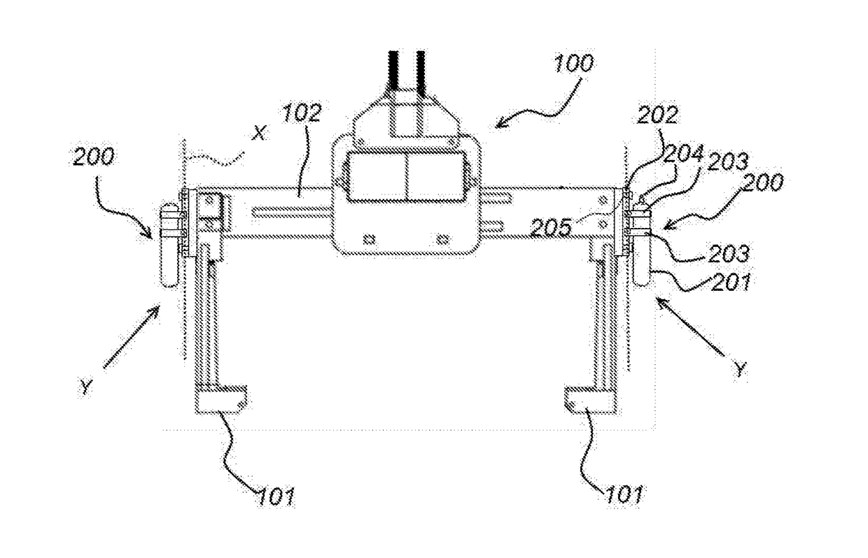
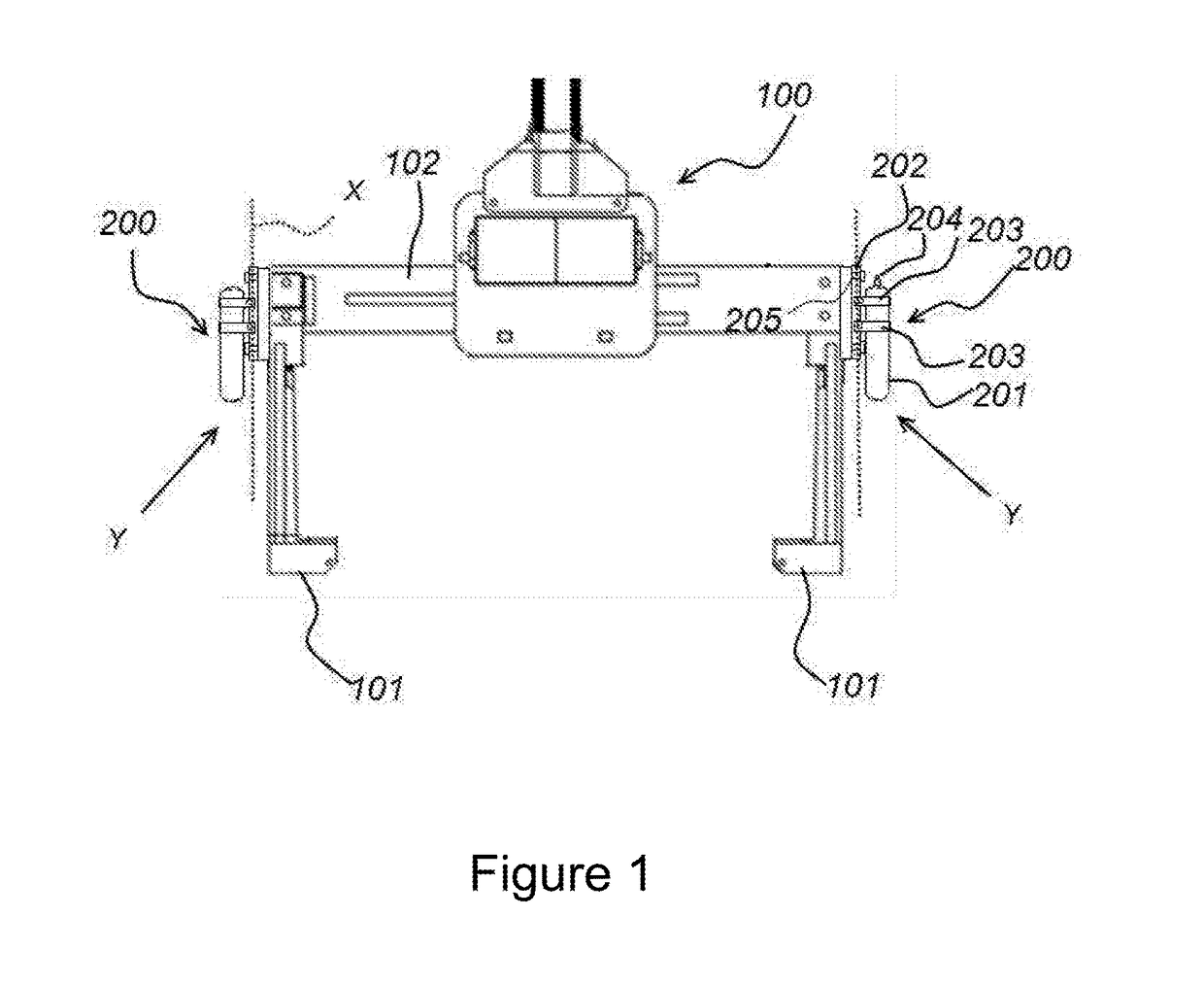
[0029]FIG. 1 illustrates the view of the crane attachment (100) comprising movable arms (101) and a slide (102) which embeds the lateral linear motion of said arms. A laser pointer (200) is integrated for allowing the projection of said crane attachment (100) to be marked lineally on the ground, the crane operator to see the exact point where s / he will unload the material, and the material to be placed.

[0030]FIG. 1 illustrates a laser source (201) adapted to the lateral sections (Y) of the crane attachment (100) in the vertical axis (X). An anti-vibration member (202) is located between the laser source (201) and the slide (102) body by means of the connection members (205). Likewise, connecting clips (203) are provided which secure said laser source (201) to the anti-vibration member (202).

[0031]The laser source (201) which is secured to the crane attachment (100) by means of the connecting clips (203) makes the required marking at the projection of the crane attachment (100) when ...


PUM


Abstract

A crane attachment having movable arms and a slide which embeds the lateral linear motion of the arms, the attachment having a laser pointer which allows the projection of the crane attachment to be marked lineally on the ground, allowing the crane operator to see the exact point where s/he will unload the material, and the material to be placed.

Description

TECHNICAL FIELD[0001]The present invention is related to a crane used for transporting the materials from one place to another and stocking the same and to the attachments of these cranes.[0002]The present invention is related to a crane attachment integrated with a laser pointer which allows the projection of the crane apparatus to be marked lineally on the ground, the crane operator to see the exact point where s / he will unload the material, and the material to be placed.PRIOR ART[0003]The cranes are mechanical configurations which are used for material transportation, also for unloading the material being transported in a determined place and stocking the same. The operator who uses the crane determines the point where s / he will stop the material being transported in the air and lower the same with the accuracy only allowed by her / his experience. In general, it is not exactly known whether the material will fit into the determined place or not before unloading the material or app...

Claims


Application Information

Patent Timeline
IPC IPC(8): B66C13/16B66C1/42
CPCB66C1/42B66C13/16B66C13/46
Inventor SUSUZLU, MEVLUT EMRAH
Owner BORCELIK CELIK SANAYI TICARET ANONIM SIRKETI
Why Eureka
Try Eureka