Omni-directional television antenna with WIFI reception capability

a television antenna and wifi reception technology, applied in the field of television antennas, can solve the problems of inability to adjust the length and direction of the dipole elements, the physical dimension of the vhf dipole is undesirably long, and the performance of such conventional indoor vhf/uhf antennas may change in response, so as to achieve the effect of expanding the range of wifi signals

Active Publication Date: 2017-05-11
VOXX INT CORP
View PDF0 Cites 23 Cited by
  • Summary
  • Abstract
  • Description
  • Claims
  • Application Information

AI Technical Summary

Benefits of technology

[0014]In another form of the present invention, the television antenna may further include two additional antenna elements for receiving WiFi signals so that the antenna of the present invention provides a WiFi Access Point (AP), or alternatively a WiFi repeater or WiFi range extender circuit, whereby a user who connects the antenna of the present invention to his monitor or television, especially a “smart” television, may watch live streaming video content. Each of the WiFi antenna elements is preferably formed as a combination of helix antenna and coaxial sleeve antenna. The WiFi repeater or WiFi extender circuit, if included, rebroadcasts or retransmits the signals received by the WiFi antennas to extend the range of the WiFi signals.

Problems solved by technology

One problem associated with the conventional indoor antenna systems is that the physical dimension of the VHF dipole is undesirably long for the ordinary setting in a living room and that the length as well as the direction of the dipole elements may need to be adjusted depending upon the receiving channels.
The second problem is that the performance of such conventional indoor VHF / UHF antennas changes in response to changes of the physical conditions around the antenna elements.
For example, it is difficult for a user to make proper adjustment of the antennas since a human body coming into contact with an antenna changes the electromagnetic conditions associated with the antenna elements.
The third problem is that the conventional indoor antenna systems do not always provide a sufficient signal level for good reception.

Method used


Image

  • Omni-directional television antenna with WIFI reception capability
  • Omni-directional television antenna with WIFI reception capability
  • Omni-directional television antenna with WIFI reception capability

Examples


Embodiment Construction

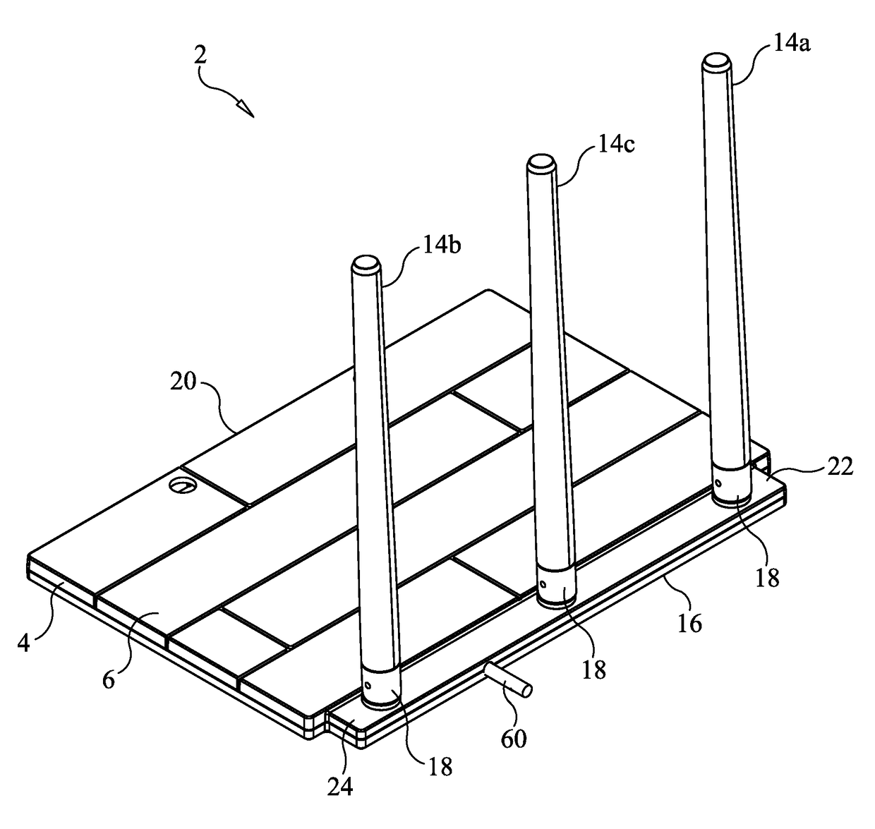
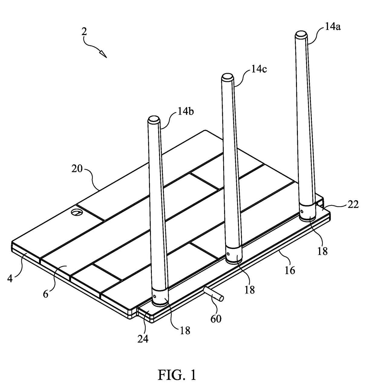
[0059]Referring initially to FIGS. 1-20 of the drawings, it will be seen that a three-pole version of an antenna 2 for receiving broadcast television signals in the VHF and UHF bands includes a substantially planar housing 4 having a top surface 6 and an opposite bottom surface 8 and defining an internal cavity in which the associated circuitry of the antenna is situated, as will be described in greater detail. The circuitry is mounted on a printed circuit board 12 situated within the internal cavity of the housing 4, which printed circuit board 12 includes one or more ground planes 13 which act as a reflective element for the UHF, VHF and WiFi antenna elements 14.

[0060]Mounted on the top surface 6 of the housing 4 of the antenna 2 are three spaced apart antenna elements 14, at least in the first form of the television antenna 2 being currently described. More specifically, the antenna elements 14 are mounted on the top surface 6 of the housing 4 in proximity to a first lateral side...


PUM


Abstract

An antenna device includes a housing defining an interior cavity, a UHF antenna element, two VHF antenna elements and two WiFi antenna elements. The antenna elements are mounted to the housing and are selectively adjustable between a vertical, upright position and a folded, horizontal position. The antenna elements are situated on the housing to provide an omni-directional antenna pattern for receiving broadcast signals. Antenna circuitry provided within the interior cavity of the housing receives signals from the antenna elements and generates an output signal that is provided to at least one output connector mounted on the housing or on one or more signal cables extending therefrom and to an external electronic device connected thereto.

Description

CROSS-REFERENCE TO RELATED APPLICATIONS[0001]This application is related to U.S. Provisional Patent Application Ser. No. 62 / 254,012, filed on Nov. 11, 2015, and entitled “Omni-Directional Television Antenna With WiFi Reception Capability”, the disclosure of which is hereby incorporated by reference and on which priority is hereby claimed.BACKGROUND OF THE INVENTION[0002]Field of the Invention[0003]The present invention generally relates to antennas for receiving broadcast signals such as television signals, and more specifically relates to television antennas for receiving digitally formatted broadcast signals.[0004]Description of the Prior Art[0005]Conventional indoor TV antenna systems generally include two separate antennas for respective VHF and UHF reception. The antenna for receiving the VHF bands employs a pair of telescopic elements forming a dipole with each of the elements having a maximum length of from four to six feet (1.5 to 2.5 meters). The two elements usually are mo...

Claims


Application Information

Patent Timeline
Patent Type & Authority Applications(United States)
IPC IPC(8): H01Q9/26H01Q1/26H01Q1/50H01Q7/00H01Q1/22
CPCH01Q9/26H01Q7/00H01Q1/26H01Q1/50H01Q1/2291H01Q1/084H01Q1/10H01Q9/32H01Q11/08H01Q21/28H01Q1/362
Inventor TINAPHONG, PRAPAN PAULRINEHART, JAMES K.HUNG, CHUNG HUA
Owner VOXX INT CORP
Why Eureka
Try Eureka