
Method for controlling an internal combustion engine

a technology of internal combustion engine and control method, which is applied in the direction of electric control, machines/engines, mechanical equipment, etc., can solve the problem of the risk of a temporary rise in the temperature of the engine block above the permitted temperature threshold, and achieve the effect of reducing fuel consumption and limited engine temperature ris

Inactive Publication Date: 2017-05-18
RENAULT SA
View PDF2 Cites 1 Cited by
  • Summary
  • Abstract
  • Description
  • Claims
  • Application Information

AI Technical Summary

Benefits of technology

The present invention proposes a method to control the temperature of the engine block to reduce fuel consumption. It does this by controlling the temperature of the liquid coolant and the amount of fuel injected into the cylinders. This approach ensures that the engine block stays cool and prevents it from overheating. As a result, fuel consumption is reduced and engine efficiency is improved.

Problems solved by technology

These two phenomena combined lead to a risk of a temporary rise in the temperature of the engine block beyond the permitted temperature threshold.

Method used


Image

  • Method for controlling an internal combustion engine
  • Method for controlling an internal combustion engine
  • Method for controlling an internal combustion engine

Examples


Embodiment Construction

[0034]The description given below in relation to the attached drawings refers to merely non-limitative examples, and will illustrate clearly the content of the invention and show how it may be implemented.

[0035]On the attached drawings:

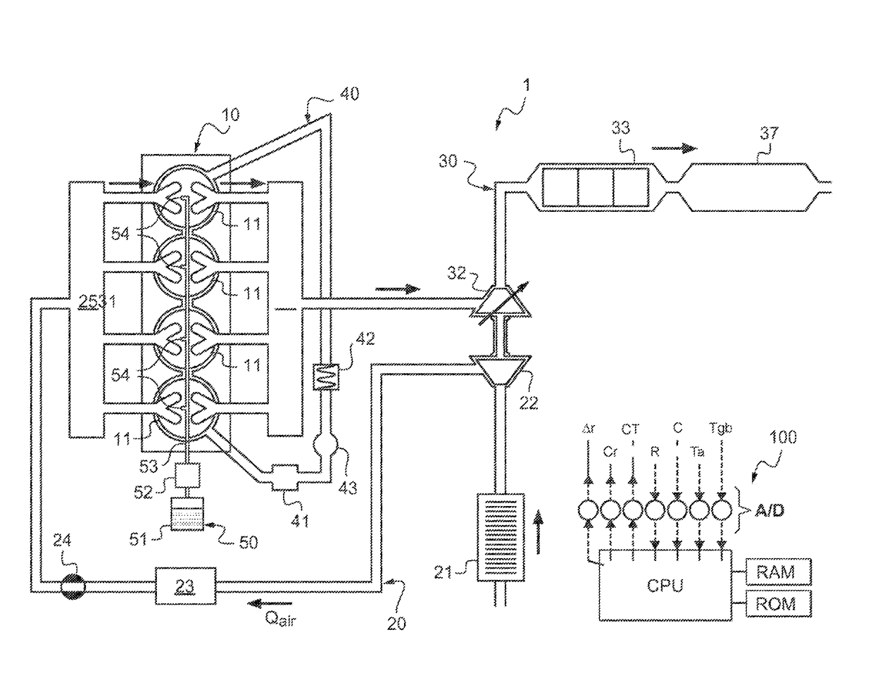
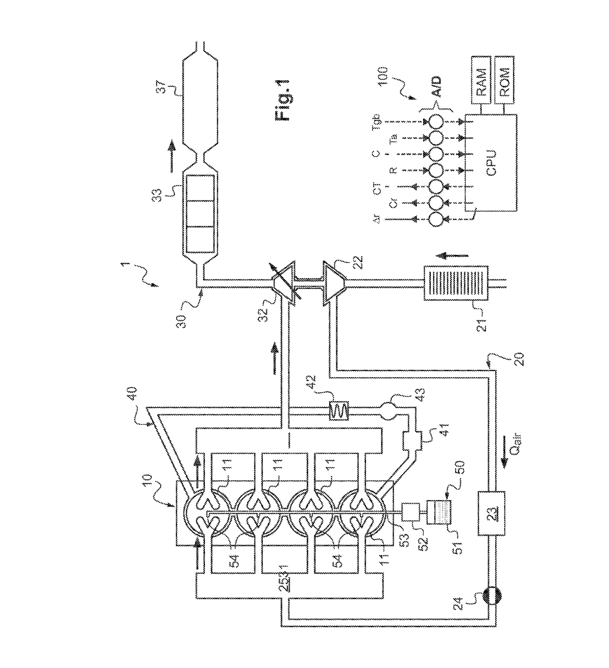
[0036]FIG. 1 is a diagrammatic view of an internal combustion engine according to the invention, and

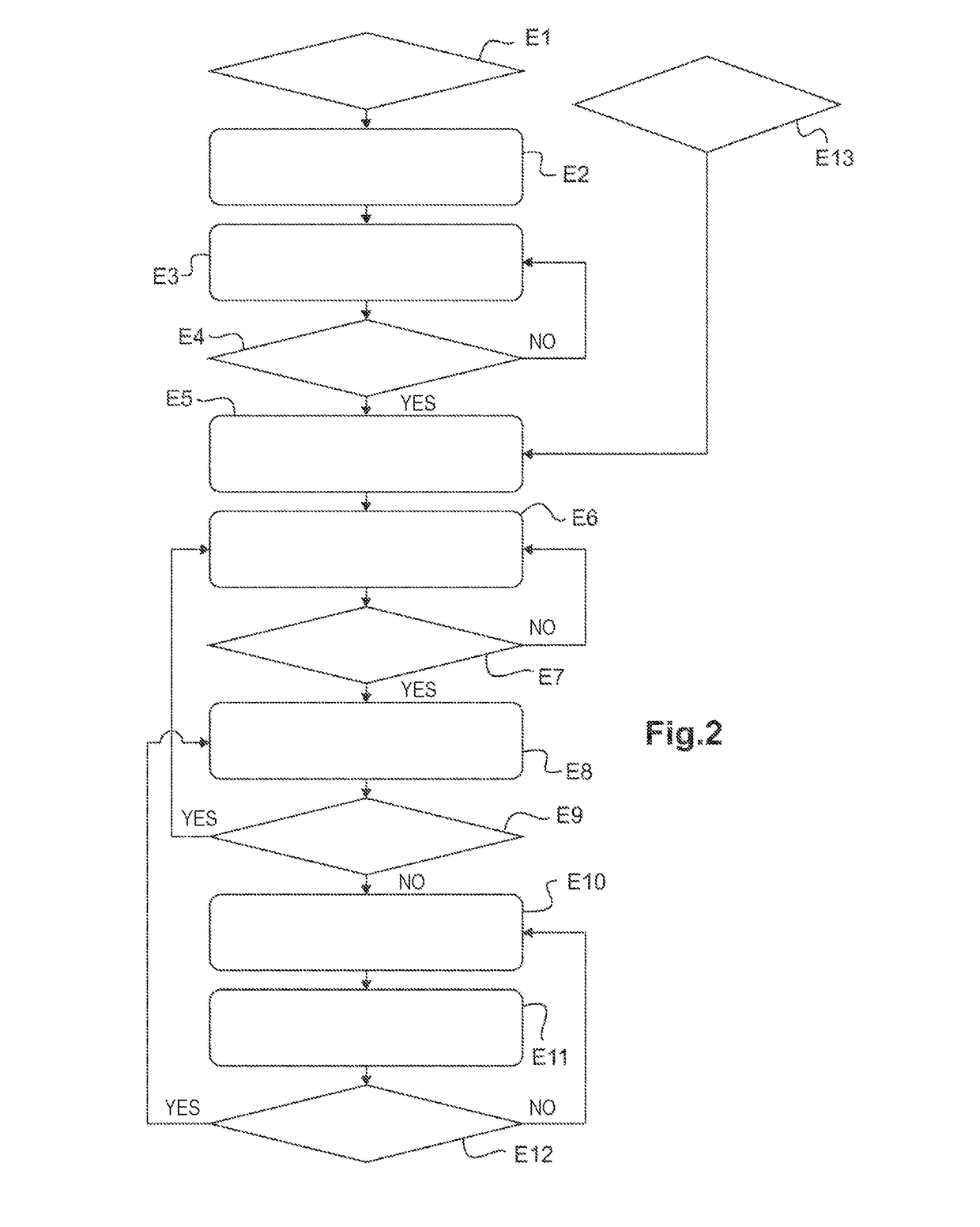
[0037]FIG. 2 is a diagram illustrating the steps of the method used to control the internal combustion engine in FIG. 1.

[0038]In the description, the terms “upstream” and “downstream” are used according to the direction of gas flow from the point of intake of fresh air from the atmosphere to the outlet of the burned gas to the atmosphere.

[0039]FIG. 1 shows diagrammatically an internal combustion engine 1 of a motor vehicle, which comprises an engine block 10 provided with a crankshaft and four pistons (not shown) housed in four cylinders 11.

[0040]This engine here has controlled ignition. It may also have compression ignition.

[0041]Upstream of the cylind...


PUM


Abstract

A method for controlling an internal combustion engine includes acquiring, at a first operating point of the engine, a value of a first characteristic parameter of the first operating point, and deducing from the value a first liquid coolant temperature setpoint in the engine and a first richness setpoint of a mixture of air and fuel to be admitted into the engine. The method also includes acquiring, on passing a second operating point different from the first, the value of the parameter and deducing from the value, second setpoints for temperature and richness. When the second temperature setpoint is strictly lower than the first temperature setpoint, the method includes determining an additional richness to be added to the second richness setpoint, acquiring a burned gas temperature, and progressively reducing the additional richness as a function of the burned gas temperature acquired.

Description

TECHNICAL FIELD TO WHICH THE INVENTION RELATES[0001]The present invention generally concerns the field of internal combustion engines.[0002]More particularly, it concerns a method for controlling an internal combustion engine wherein[0003]at a first operating point of the internal combustion engine, the value of a first characteristic parameter of said operating point is acquired, and from this a first liquid coolant temperature setpoint in the internal combustion engine and a first richness setpoint of the mixture of air and fuel to be admitted into the internal combustion engine are deduced,[0004]on passing a second operating point different from the first operating point, the value of said parameter is acquired and from this, second setpoints for temperature and richness are deduced.[0005]It also concerns an internal combustion engine comprising an engine block, an intake line for introducing fresh air into the engine block and provided with a valve for controlling the flow of fr...

Claims


Application Information

Patent Timeline
Patent Type & Authority Applications(United States)
IPC IPC(8): F01P7/16F02D41/40F02D41/14
CPCF01P7/167F02D41/1446F02D2200/0414F01P2025/08F02D41/40F02D41/10F02D2200/602F02D2200/021F02D41/0007Y02T10/40
Inventor PETILLON, YOHANN
Owner RENAULT SA
Learn More