Vehicle lighting device

a technology for lighting devices and vehicles, applied in semiconductor devices, light sources, lighting and heating equipment, etc., can solve the problems of insufficient light and inability to achieve a higher resolution of the projected light distribution pattern, and achieve the effect of increasing the size of the light-deflecting mirror and achieving the resolution of the light distribution pattern

Active Publication Date: 2017-05-18
STANLEY ELECTRIC CO LTD
View PDF8 Cites 20 Cited by
  • Summary
  • Abstract
  • Description
  • Claims
  • Application Information

AI Technical Summary

Benefits of technology

[0007]An object of the present invention is to provide a vehicle lighting device capable of achieving a higher resolution of a light distribution pattern without increasing the size of a light-deflecting mirror.

Problems solved by technology

A single light source cannot provide a sufficient amount of light required of such a vehicle lighting device, so that a plurality of light sources are used.
If the light-deflecting mirror is made larger, then the motion thereof will be slower, thus it is not possible to obtain a higher resolution of the projected light distribution pattern.

Method used


Image

  • Vehicle lighting device
  • Vehicle lighting device
  • Vehicle lighting device

Examples


first embodiment

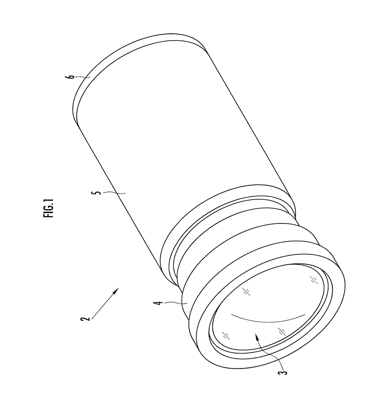
[0036]Referring to FIG. 1, a vehicle lighting device 2 has a projector lens 3, a lens holder 4 which holds the projector lens 3, a main body barrel 5 attached to the rear end of the lens holder 4, and a bottom cover 6 which closes the opening on the rear side of the main body barrel 5. In the present embodiment, the vehicle lighting device 2 is used as, for example, a headlight of a vehicle.

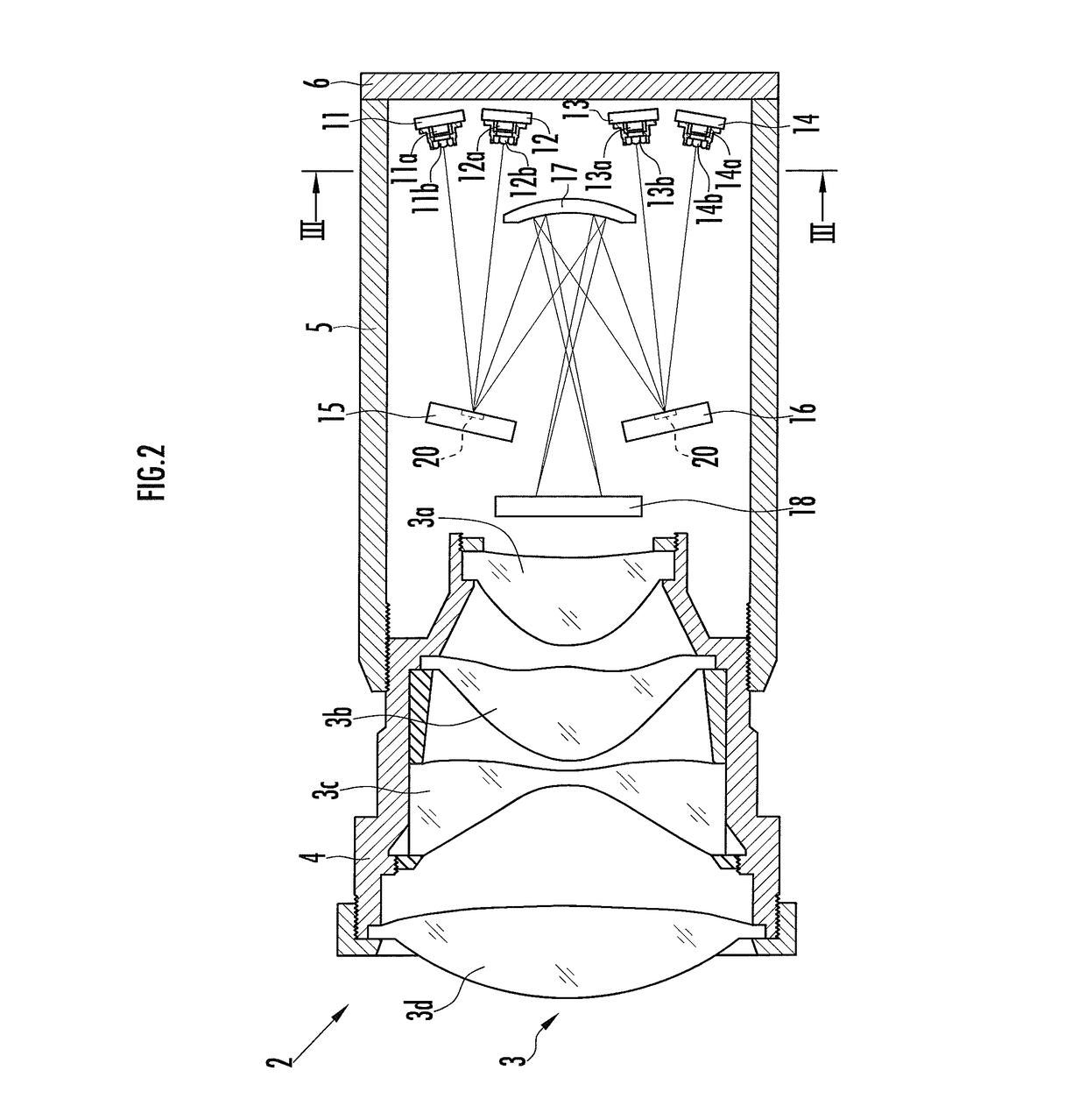
[0037]Referring to FIG. 2, the vehicle lighting device 2 has a first to a fourth excitation light sources 11 to 14, an upper light deflector 15, which scans the excitation light beams from the first and the second excitation light sources 11 and 12 in a two-dimensional manner (in a horizontal direction and a vertical direction), and a lower light deflector 16, which scans the excitation light beams from the third and the fourth excitation light sources 13 and 14 in the two-dimensional manner. Hereinafter, the upper light deflector 15 and the lower light deflector 16 will be combined and referred ...

second embodiment

[0093]In the embodiment illustrated in FIG. 9 and FIG. 10, a vehicle lighting device 40 is equipped with a first to a fourth excitation light sources 11 to 14, an upper light deflector 15 and a lower light deflector 16, but not equipped with the correction mirror 17. The first and the second excitation light sources 11 and 12 emit light beams toward the rotational center of a light-deflecting mirror 20 of the upper light deflector 15, while the third and the fourth excitation light sources 13 and 14 emit light beams toward the rotational center of a light-deflecting mirror 20 of the lower light deflector 16. The constituent members that are the same as those in the foregoing embodiment will be assigned the same reference symbols and the detailed descriptions thereof will be omitted.

[0094]As illustrated in FIG. 10A, a laser beam emitted from the first excitation light source 11 is scanned in the horizontal direction and the vertical direction by the upper light deflector 15 and then ...

third embodiment

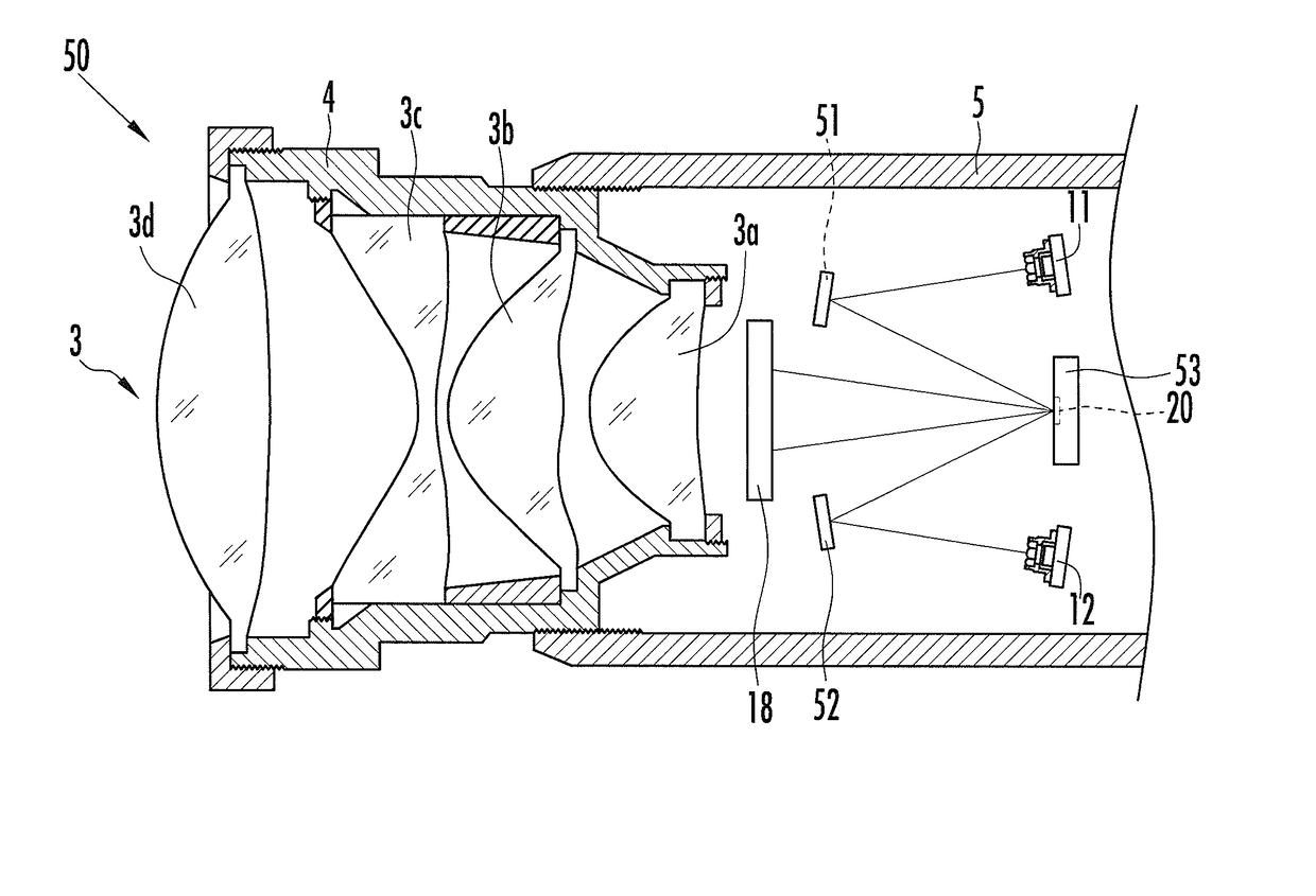
[0101]According to the embodiment illustrated in FIG. 11 and FIG. 12, a vehicle lighting device 50 has a first reflection mirror 51, a second reflection mirror 52, and a light deflector 53 having the same configuration as that of the upper light deflector 15. The constituent members that are the same as those in the foregoing embodiments will be assigned the same reference symbols and the detailed descriptions thereof will be omitted.

[0102]The first reflection mirror 51 reflects a laser beam emitted from the first excitation light source 11 toward the rotational center of a light-deflecting mirror 20 of the light deflector 53. The second reflection mirror 52 reflects a laser beam emitted from the second excitation light source 12 toward the rotational center of the light-deflecting mirror 20 of the light deflector 53. Alternatively, only one reflection mirror may be provided and the two light beams emitted from the first and the second excitation light sources 11 and 12 may be refle...


PUM


Abstract

A vehicle lighting device includes a projector lens, a lens holder, a main body barrel, a bottom cover, a first to a fourth excitation light sources, an upper and a lower light deflector, a correction mirror, and a fluorescent unit. The first and the second excitation light source emit laser beams toward the rotational center of a light-deflecting mirror of the upper light deflector, and the third and the fourth excitation light source emit laser beams toward that of the lower light deflector. The correction mirror corrects the distortion of the laser beams scanned by the upper and lower light deflectors and reflects the corrected laser beams. A two-dimensional image corresponding to a predetermined light distribution pattern is drawn as a white image on the fluorescent unit by the corrected light beams, and the two-dimensional image is projected on a virtual vertical screen through the projector lens.

Description

BACKGROUND OF THE INVENTION[0001]Field of the Invention[0002]The present invention relates to a vehicle lighting device equipped with a light deflector that scans light beams.[0003]Description of the Related Art[0004]As a vehicle lighting device to be mounted on a vehicle, there is one adapted to scan a light beam from a light source, such as a laser, by a light deflector, such as a microelectromechanical system (MEMS), draw a two-dimensional image on a fluorescent screen, and project at front the two-dimensional image in the form of a light distribution pattern. A single light source cannot provide a sufficient amount of light required of such a vehicle lighting device, so that a plurality of light sources are used.[0005]For example, according to the vehicle lighting device described in Japanese Patent No. 4881255, light beams are emitted from three light sources to different parts of a light-deflecting mirror of a light deflector, and the light-deflecting mirror is rotated in this...

Claims


Application Information

Patent Timeline
Patent Type & Authority Applications(United States)
IPC IPC(8): F21S8/10B60Q1/14
CPCF21S48/1757F21S48/1388F21Y2115/30B60Q1/14F21S48/125F21S41/16F21S41/176F21S41/33F21S41/365F21S41/25F21S41/675
Inventor HIRASAWA, HIROSHIYATSUDA, YASUSHI
Owner STANLEY ELECTRIC CO LTD
Why Eureka
Try Eureka