Image forming device and program

a technology of image forming and program, which is applied in the direction of electrographic process equipment, optics, instruments, etc., can solve the problems of reducing productivity, canceling useless jobs, and affecting the production of blank parts, so as to suppress the generation of blank parts and suppress the effect of lowering productivity

Active Publication Date: 2017-05-18
KONICA MINOLTA INC
View PDF43 Cites 5 Cited by
  • Summary
  • Abstract
  • Description
  • Claims
  • Application Information

AI Technical Summary

Benefits of technology

[0011]The present invention has been made in view of such problems. An object of the present invention is to provide an image forming device and a program capable of suppressing generation of blank portions on continuous paper due to toner refreshing and suppressing lowering of the productivity.

Problems solved by technology

In an electrophotographic image forming system, when the toner in the developing device is deteriorated, a problem such as degradation of image quality or toner spilling is caused.
However, when attempting to apply the aforementioned technology to continuous paper, as a refresh band is created at an unexpected portion between images on the sheets, it is not preferable.
However, an interruption process or the like is involved, whereby blank portions (gaps between images) are generated at a plurality of locations on the continuous paper, which lowers the productivity.
Even in such a situation, with a configuration in which a refresh band is created whenever the upper limit value is reached, a user may cancel the job uselessly, which leads to lowering of the productivity.

Method used


Image

  • Image forming device and program
  • Image forming device and program
  • Image forming device and program

Examples


Embodiment Construction

[0021]Hereinafter, an embodiment of the present invention will be described with reference to the drawings. However, the scope of the invention is not limited to the illustrated examples.

[0022]First, a configuration of an image forming system of the present embodiment will be described.

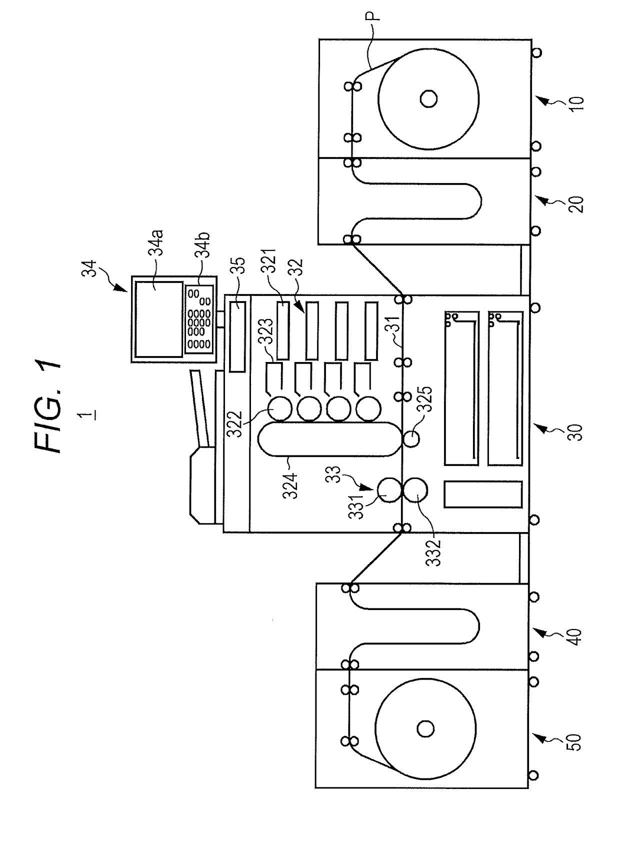
[0023]FIG. 1 is a diagram illustrating an exemplary schematic configuration of an image forming system 1.

[0024]The image forming system 1 is a system that uses continuous paper (rolled paper) P as a recording medium and forms an image on the continuous paper P.

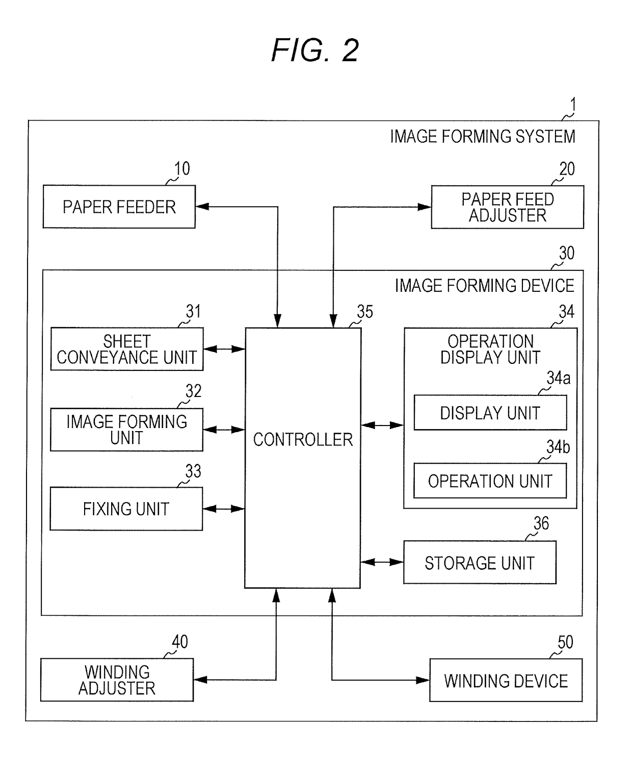
[0025]As illustrated in FIG. 1, the image forming system 1 includes a paper feeder 10, a paper feed adjuster 20, an image forming device 30, a winding adjuster 40, and a winding device 50 which are connected with each other from the upstream side along a direction of conveying the continuous paper P.

[0026]The paper feeder 10 is a device for feeding the continuous paper P to the image forming device 30. As illustrated in FIG. 1, in the casing of ...


PUM


Abstract

An image forming device includes: an image forming unit configured to form a plurality of images on continuous paper based on a job; an image pattern creation unit configured to interrupt execution of the job and create an image pattern for consuming toner; a determination unit configured to determine necessity of creating the image pattern based on coverages of the images included in the job; and a calculation unit configured to, when the determination unit determines that it is necessary to create the image pattern, calculate a conveyance distance or a conveyance time of the continuous paper until creation of the image pattern, as interruption timing.

Description

[0001]The entire disclosure of Japanese Patent Application No. 2015-225286 filed on Nov. 18, 2015 including description, claims, drawings, and abstract are incorporated herein by reference in its entirety.BACKGROUND OF THE INVENTION[0002]Field of the Invention[0003]The present invention relates to an image forming device and a program.[0004]Description of the Related Art[0005]In an electrophotographic image forming system, when the toner in the developing device is deteriorated, a problem such as degradation of image quality or toner spilling is caused. As such, the toner in the developing device is replaced in a certain amount or more when a certain period of time passes (which is called toner refreshing).[0006]For example, a technology has been proposed in which when image formation of low coverage images is continued with use of cut sheets of paper, an image pattern named refresh band is created between sheets to forcibly consume toner to thereby replace the toner in the developi...

Claims


Application Information

Patent Timeline
Patent Type & Authority Applications(United States)
IPC IPC(8): G03G15/00
CPCG03G15/5012G03G15/5062G03G2215/0135
Inventor NISHI, YOUICHIROU
Owner KONICA MINOLTA INC
Why Eureka
Try Eureka