Electrical connection device, terminal block including same, photovoltaic power generation system, and electrical appliance

a technology of electrical connection device and terminal block, which is applied in the direction of threaded fasteners, coupling device connections, screws, etc., can solve the problems of affecting the work efficiency of workers, affecting the reliability of electrical connections, etc., to achieve the effect of high reliably preventing insufficient tightening of a male portion and extreme eas

Active Publication Date: 2017-05-18
KITANI ELECTRIC
View PDF0 Cites 0 Cited by
  • Summary
  • Abstract
  • Description
  • Claims
  • Application Information

AI Technical Summary

Benefits of technology

[0016]According to the electrical connection device of the present invention, it is possible to highly reliably prevent insufficient tightening of a male portion at the time of fastening while enabling a worker to at least tactually determine a fastening condition of the male portion with extreme ease.

Problems solved by technology

In such a case, failing to confirm a fastening degree of the bolt increases a possibility that various problems occur due to insufficient electrical connection.
Additionally, when working in a dark place or a limited area, a worker may have a difficulty in confirming a final fastening degree of a bolt.
In particular, since a recent photovoltaic power generation system, which is represented by a term, mega solar, includes numerous terminal blocks, for example, the above-described work using a bolt for electrical connection may be a considerable work-load for workers.

Method used


Image

  • Electrical connection device, terminal block including same, photovoltaic power generation system, and electrical appliance
  • Electrical connection device, terminal block including same, photovoltaic power generation system, and electrical appliance
  • Electrical connection device, terminal block including same, photovoltaic power generation system, and electrical appliance

Examples


first embodiment

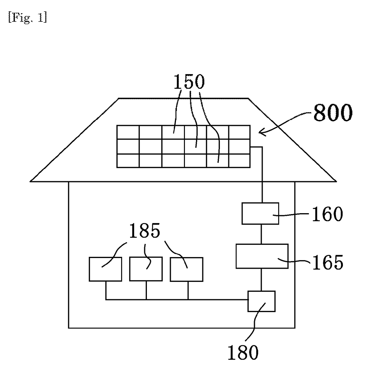
[0089]FIG. 1 is a schematic view showing a configuration of a photovoltaic power generation system 800 having a terminal block 110 including an electrical connection device 100 according to the present embodiment. As shown in FIG. 1, the photovoltaic power generation system 800 includes, for example, a plurality of solar cell modules 150 installed on a roof of a house, a connection box 160, and a power conditioner 165 which converts DC power generated by the solar cell module 150 to AC power. Power generated by the photovoltaic power generation system 800 is supplied to various electrical appliances 185 via a distribution panel 180. In the present embodiment, the solar cell modules 150 each including a plurality of solar battery cells are all disposed on the same plane. Additionally, the plurality of the solar cell modules 150 are electrically connected in series or in parallel to each other via the electrical connection device 100.

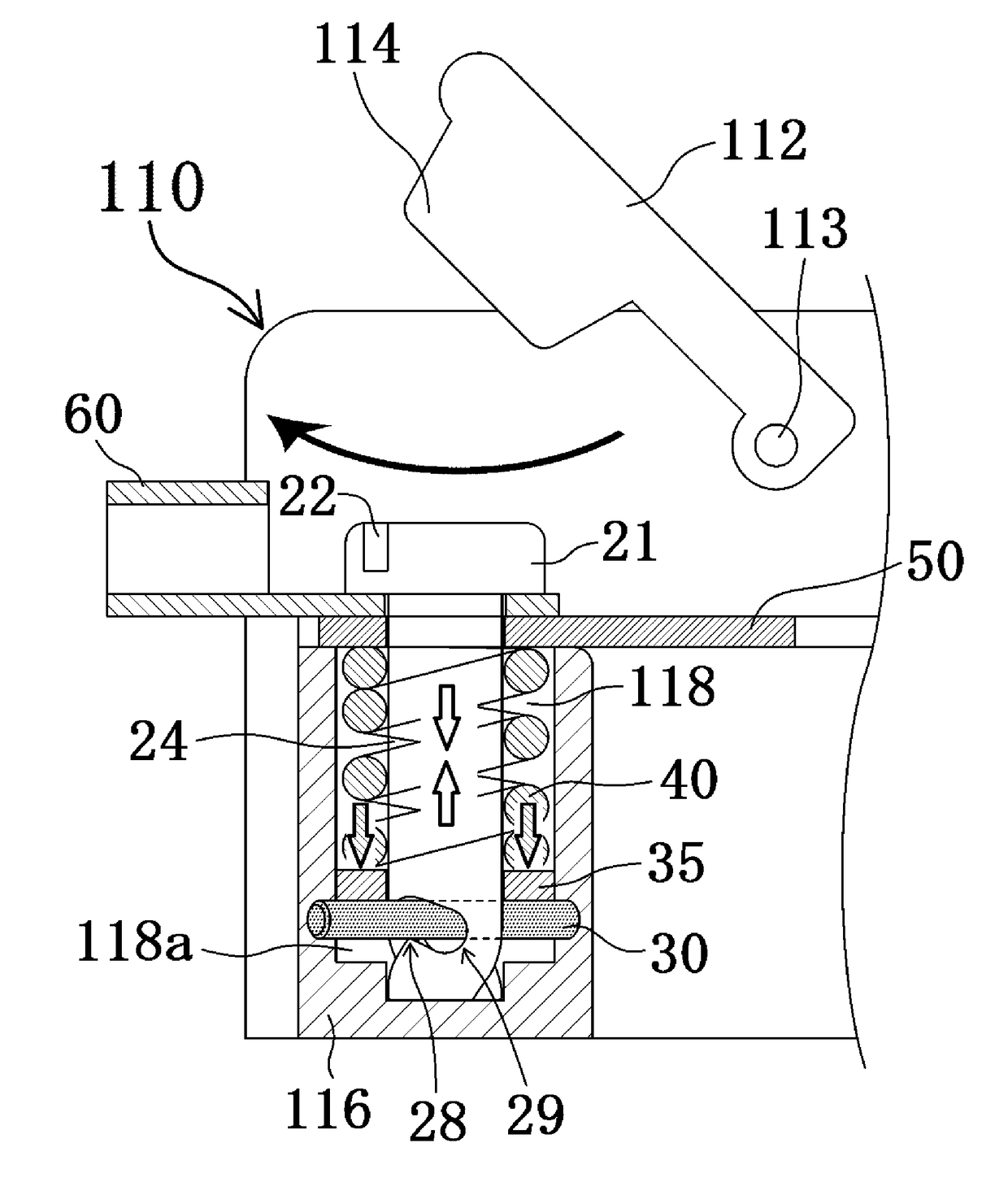
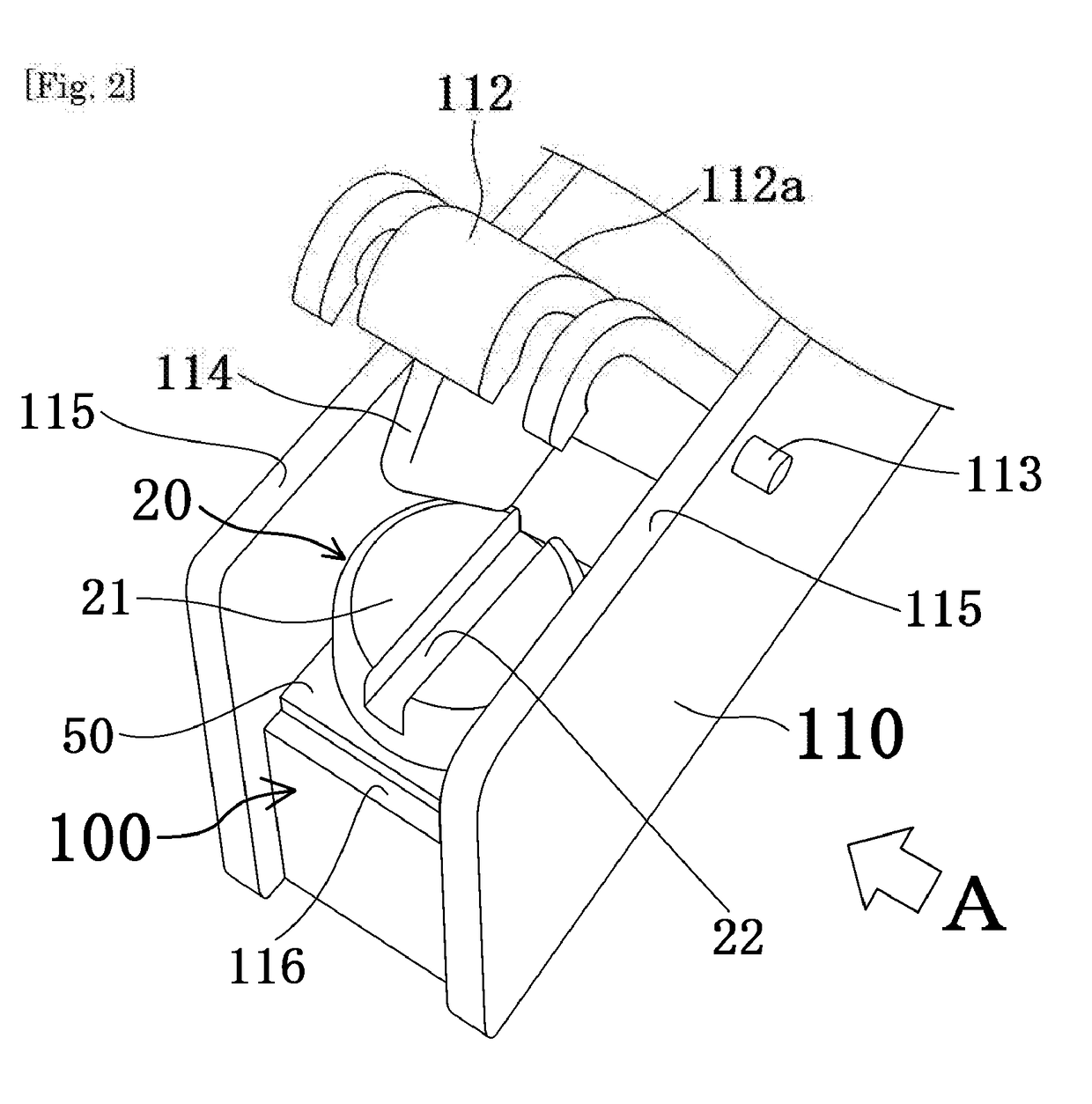
[0090]FIG. 2 is a perspective view schematically sh...

second embodiment

[0107]In the present embodiment, an electrical connection device and a terminal block are the same as the electrical connection device 100 and the terminal block 110 of the first embodiment, except that the bolt 20, the lid body 112 provided in the terminal block 110, and a mechanism which causes a change in a biasing force of the coil spring 40 of the first embodiment are changed. Accordingly, description overlapping with that of the first embodiment will be omitted.

[0108]FIG. 12A shows a front view, a left side view, and a vertical sectional view seen from the front (more specifically, a vertical sectional view of the center of a body portion 224 in a depth direction of the plane of drawing in FIG. 12A) of a shape of a bolt 220 as one example of a male portion according to the present embodiment. FIG. 12B is a perspective view showing the shape of the bolt 220 according to the present embodiment. FIG. 13 to FIG. 15 are partial sectional side views for explaining a step of fastenin...

third embodiment

[0123]The present embodiment has a mode in which in the first embodiment, a bolt 320 is adopted in place of the bolt 20. FIG. 20 is a perspective view showing a shape of the bolt 320 of the present embodiment, which corresponds to FIG. 4.

[0124]As shown in FIG. 20, the bolt 320 of the present embodiment includes a head 321 having a cross-shaped driver groove 322 in which a driver is inserted to turn the bolt 320, and a body portion 24 having the same configuration as that of the body portion 24 of the bolt 20 in the first embodiment. Even with the bolt 320 of such a mode, at least a part of the effects of the first embodiment can be obtained.

[0125]However, for enabling a worker to visually recognize a tightening condition of the bolt with ease, it is more preferable to adopt a linear driver groove than the cross-shaped driver groove 322. Needless to say, in the second embodiment or a fourth embodiment to be described later, a bolt including a head having the cross-shaped driver groov...


PUM


Abstract

There is provided an electrical connection device (100) including a male portion including a head (21) having a groove for insertion of a driver, and a body portion (24) having a spirally penetrating first guide hole (26a) formed from a lower end and a second guide hole (26b); a female portion (116) having a hole portion (118) into which the body portion (24) is inserted; an elastic portion (40) to be disposed on an outer circumference of the body portion (24) when the body portion (24) is inserted into the hole portion (118); and a movable body (30) which is disposed below the elastic portion, and engages and penetrates through the first guide hole (26a) when the body portion (24) is inserted into the hole portion (11), in which a first conductive member (50) and a second conductive member (60) are interposed between an upper end of the elastic portion (40) and the head (21), and with the movable body (30) engaged in the first guide hole (26a), as the head (21) rotates to a predetermined rotation angle relative to the hole portion (118), a biasing force of the elastic portion (40) is increased due to a rise of the movable body (30) in contact with a lower end of the elastic portion (40), and when a rotation angle of the head (21) relative to the hole portion (118) exceeds the predetermined rotation angle, the movable body (30) engages in an end portion (29) of a second guide hole (26b) leading to the first guide hole (26a), the second guide hole being provided in a direction in which the biasing force is reduced, to suppress rotational movement of the movable body (30) relative to the body portion (24).

Description

TECHNICAL FIELD[0001]The present invention relates to an electrical connection device and a terminal block including the same, a photovoltaic power generation system, and an electrical appliance.BACKGROUND ART[0002]For example, in wiring connection inside various electrical appliances or in connection between various electrical appliances, as shown in FIG. 24, electrical connection work is conducted using a terminal block 900, which is divided into a plurality of sections by walls 90, 92, to fasten a lead line and a conductive plate 94 by a bolt 922 with a washer 98 provided therebetween.[0003]On this occasion, a worker required to conduct bolt fastening work for numerous terminals or a worker required to conduct such work for a long period of time often needs more time for confirming that each bolt is securely fastened or not. Additionally, from a point of view of workability, a worker may insert a driver into a groove 922 of a bolt 921 and conduct so-called temporary fixing, that ...

Claims


Application Information

Patent Timeline
Patent Type & Authority Applications(United States)
IPC IPC(8): H01R9/24H02S40/34
CPCH02S40/34H01R9/2416H01R9/22F16B21/02F16B35/044H01R4/42H01R4/52H01R4/54H01R11/12H01R13/447H01R13/213Y02E10/50F16B2200/93
Inventor TAKASHIMA, YUICHI
Owner KITANI ELECTRIC
Why Eureka
Try Eureka