Component mounting device

a technology of mounting device and component, which is applied in the direction of electrical components, electrical apparatus, etc., can solve the problems of increased mounting time, process may not be carried out, and difficult to complete the rotation during, so as to reduce the waiting time, shorten the mounting time, and improve production efficiency

Active Publication Date: 2017-05-18
FUJI MASCH MFG CO LTD
View PDF6 Cites 5 Cited by
  • Summary
  • Abstract
  • Description
  • Claims
  • Application Information

AI Technical Summary

Benefits of technology

[0015]In the component mounting device of one embodiment, when the movable section moves from the supply position of the component supply device to the mounting position of the target object via the imaging position of the imaging device, the control section compares the time (the first required time) which is required for the movement from the supply position to the imaging position with the time (the second required time) which is required for the movement from the imaging position to the mounting position. The control section starts the Q-axis rotation of the mounting nozzle in the movement operation with the longer required time of the two required times. According to the component mounting device, since the carrying out of the Q-axis rotation is started during the operating in which the movement time is longer among the movement operations before and after the imaging process, it becomes possible to reduce the waiting time in which the next process (a suction position correction process for the imaging process or the mounting, or the like) enters a standby state until the Q-axis rotation is completed. As a result, the component mounting device is capable of achieving a shortening in the mounting time and achieving an improvement in production efficiency. According to the component mounting device, adjustment which shortens the first required time becomes possible by optimizing the start timing of the Q-axis rotation. Therefore, it becomes possible for the component mounting device to shorten the first required time, that is, to shorten the inter-device physical distance between the component supply device and the imaging device and be disposed in close proximity thereto, and a reduction in device size may be achieved.
[0016]In the component mounting device according to another embodiment, in a case in which the rotation time in which the mounting nozzle is subjected to the Q-axis rotation is less than or equal to the first required time, the control section starts the Q-axis rotation in the movement operation from the supply position to the imaging position. In this type of component mounting device, it becomes possible to detect and correct the error which arises through the operations (the Q-axis rotation and the like) carried out by the imaging device before the imaging based on the imaging data of the imaging device. Therefore, in a case in which the mounting time is not taken into consideration, it is preferable that the component mounting device completes the Q-axis rotation before the imaging. Therefore, in a case in which the rotation time is less than or equal to the first required time, even in a case in which the second required time is long in comparison to the first required time, the control section prioritizes carrying out the Q-axis rotation before the imaging. Accordingly, the control section becomes capable of achieving both a shortening in the mounting time through optimization of the start timing of the Q-axis rotation, and an improvement in the processing precision of mounting the component onto the target object through prioritizing carrying out the Q-axis rotation before the imaging.
[0017]In the component mounting device according to another embodiment, the imaging device images the component in a state of being held at one of the imaging angles among the plurality of imaging angles which are set for every angle equally spaced in relation to the rotational angle around the Q-axis. The control section is configured to be capable of carrying out the Q-axis rotation divided into two times, from the supply position to the imaging position, and from the imaging position to the mounting position. In the movement from the supply position to the imaging position, the control section subjects the mounting nozzle to the Q-axis rotation in the first divided time to a predetermined imaging angle. In the movement from the imaging position to the mounting position, the control section subjects the mounting nozzle to the Q-axis rotation in the second divided time by the remaining rotational angle. The control section carries out the Q-axis rotation in conditions under which the required time is shortest among the three required times (first divided time−first required time+second divided time−second required time), (rotation time−first required time), and (rotation time−second required time). According to the component mounting device, the Q-axis rotation may be carried out divided into before and after the imaging, and the start timing of the Q-axis rotation is optimized to enable more reliable shortening of the mounting time.
[0018]In the component mounting device according to another embodiment, the control section includes a time which is required for the other mounting nozzles excluding the first mounting nozzle to acquire the components from the supply position after, among the plurality of mounting nozzles, the first mounting nozzle acquires the component in the first required time of the first mounting nozzle. The time in which the other mounting nozzles acquire the components after the first mounting nozzle acquires the component is a time in which it is possible for the first mounting nozzle to perform the Q-axis rotation. Therefore, in a case in which the movable section is provided with the plurality of mounting nozzles, the control section is capable of determining a more appropriate start timing of the Q-axis rotation by including the time in which the mounting nozzles are carrying out the respective suction work in the first required time for the Q-axis rotation.
[0019]In the component mounting device according to another embodiment, the control section includes a time which is required for the other mounting nozzles excluding the first mounting nozzle to mount the components onto the mounting positions before, among the plurality of mounting nozzles, the first mounting nozzle mounts the component onto the mounting position of the target object in the second required time of the first mounting nozzle. The time in which the other mounting nozzles mount the components before the first mounting nozzle mounts the component is a time in which it is possible for the first mounting nozzle to perform the Q-axis rotation. Therefore, in a case in which the movable section is provided with the plurality of mounting nozzles, the control section is capable of determining a more appropriate start timing of the Q-axis rotation by including the time in which the mounting nozzles are carrying out the respective mounting work in the second required time for the Q-axis rotation.

Problems solved by technology

However, in the component mounting machine, the shorter the distance from the supply position to the imaging position, the more difficult it becomes to complete the rotation during the movement to the imaging position when the angle of the Q-axis rotation is great.
Therefore, in the component mounting machine in which the timing of the Q-axis rotation described above is fixed, in a case in which the angle of the Q-axis rotation is great, there is a concern that the imaging process may not be carried out before the Q-axis rotation is completed, bringing about an increase in the mounting time, moreover, a reduction in production efficiency.

Method used


Image

  • Component mounting device
  • Component mounting device
  • Component mounting device

Examples


Embodiment Construction

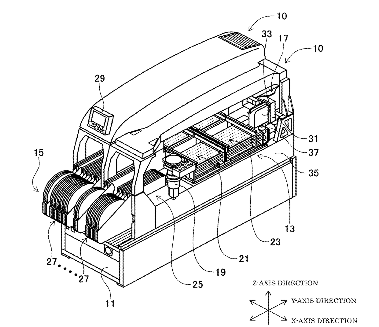
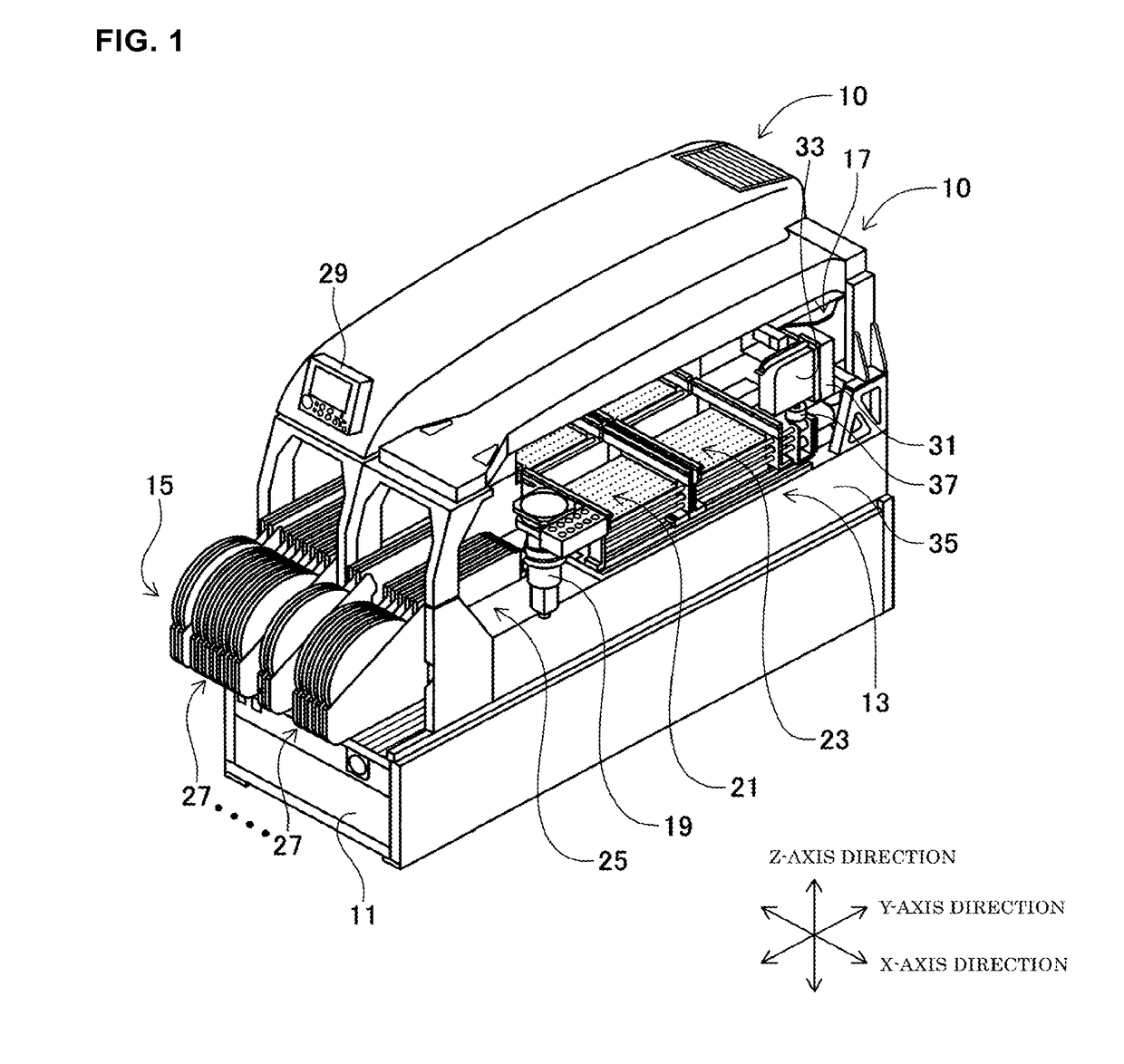
[0031]Hereinafter, an example that embodies the present disclosure will be described with reference to the drawings. FIG. 1 is a perspective diagram illustrating a component mounting machine 10 of the present example. FIG. 1 illustrates two of the component mounting machines 10 provided to line up on a shared base 11. The component mounting machine 10 is linked, for example, with other devices such as a solder printing machine, a board inspection machine, and a reflow machine to form a production line, and is a device which produces circuit boards onto which multiple electronic components are mounted. Since the two component mounting machines 10 have the same configuration, description will be given centered on one of them. In the component mounting machine 10, various devices such as a board conveyance device 13, a component supply device 15, a head driving mechanism 17, and a camera device 19 are attached onto the shared base 11. In the following description, as illustrated in FIG...


PUM


Abstract

A component mounting device with which an improvement in production efficiency may be achieved by adjusting the timing of the Q-axis rotation is provided.

Description

TECHNICAL FIELD[0001]The present application relates to a component mounting device which carries out Q-axis rotation in which an angle of a supplied component is matched to an angle at which the component is to be mounted onto a target object such as a circuit board.BACKGROUND ART[0002]In the related art, a component mounting machine which mounts electronic components onto a circuit board is an example of a component mounting device which mounts components onto a target object. For example, there is a component mounting machine in which a plurality of mounting nozzles are attached to a nozzle holder provided on a mounting head, and electronic components are sucked and held by each of the mounting nozzles. For example, a component mounting machine disclosed in PTL 1 is provided with an R-axis drive system which rotates a nozzle holder, and a Q-axis drive system which individually rotates a plurality of mounting nozzles. In the component mounting machine, the mounting nozzles which a...

Claims


Application Information

Patent Timeline
Patent Type & Authority Applications(United States)
IPC IPC(8): H05K13/04H05K13/08H05K13/02
CPCH05K13/0413H05K13/08H05K13/0408H05K13/02H05K13/0812H05K13/0813H05K13/085H05K13/0853
Inventor IISAKA, JUNOYAMA, SHIGETO
Owner FUJI MASCH MFG CO LTD
Why Eureka
Try Eureka