System of supporting turbine diffuser

a technology of supporting turbines and diffusers, which is applied in the direction of machines/engines, stators, gas turbine plants, etc., can solve the problems of increasing the wear on the diffuser section, high stress on the traditional diffuser section, so as to facilitate axial movement

Active Publication Date: 2017-05-25
GENERAL ELECTRIC CO
View PDF5 Cites 3 Cited by
  • Summary
  • Abstract
  • Description
  • Claims
  • Application Information

AI Technical Summary

Benefits of technology

[0004]In one embodiment, a system includes a circumferential lap joint between a downstream end of an outer wall of a turbine outlet and an upstream end of an outer barrel of a diffuser section, where the circumferential lap joint facilitates axial movement of the outer barrel relative to the outer wall. An upstream lip of the outer barrel is disposed radially within a downstream lip of the outer wall, and both the turbine outlet and the diffuser section are configured to receive an exhaust gas.

Problems solved by technology

Traditional diffuser sections of the turbine are subject to high stresses due to the configuration of the diffuser section and high temperatures associated with the exhaust gases.
Accordingly, traditional diffuser sections experience high stresses, thereby increasing the wear on the diffuser section.

Method used


Image

  • System of supporting turbine diffuser
  • System of supporting turbine diffuser
  • System of supporting turbine diffuser

Examples


Embodiment Construction

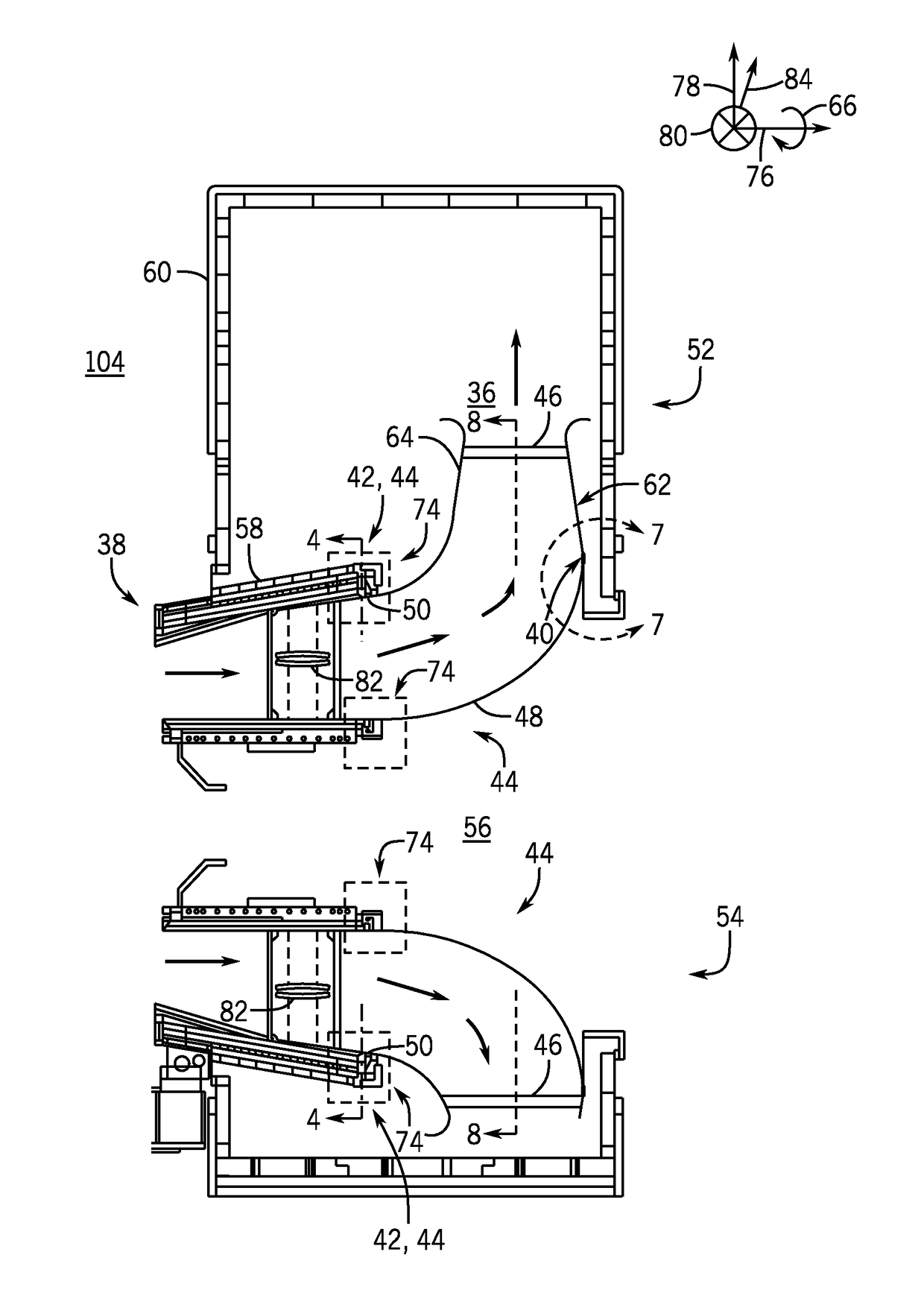
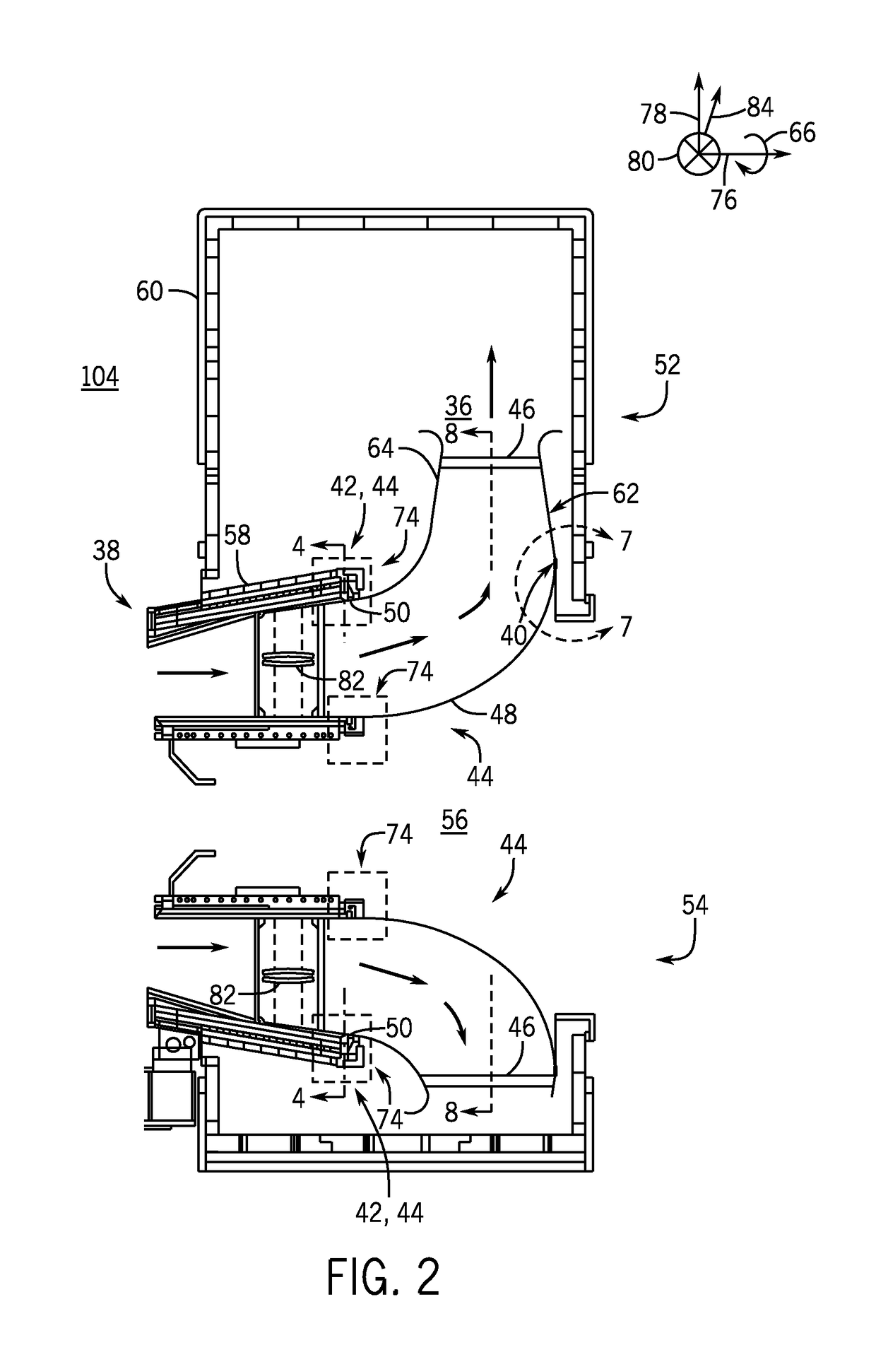
[0021]A system and methods for improving traditional diffuser sections through utilization of mechanical improvements on the diffuser section is described in detail below. The mechanical improvements to the diffuser section contribute to improved mechanical integrity of the diffuser by reducing stresses associated with a traditional diffuser design. As discussed in detail below, the embodiments of the mechanical improvements include manufacturing a desired curvature of the diffuser section, disposing a plurality of poles between a forward plate and the aft plate of the diffuser, a circumferential groove disposed in the inner barrel to receive the aft plate, a circumferential lap joint of the outer barrel, a plurality of discrete brackets disposed along the inner barrel and / or the outer barrel of the diffuser configured to couple the diffuser to the turbine outlet, or any combination thereof. The curvature of the diffuser section is implemented by a machine process, such as a spinnin...


PUM


Abstract

A system includes a circumferential lap joint between a downstream end of an outer wall of a turbine outlet and an upstream end of an outer barrel of a diffuser section, where the circumferential lap joint facilitates axial movement of the outer barrel relative to the outer wall, an upstream lip of the outer barrel is disposed radially within a downstream lip of the outer wall, and both the turbine outlet and the diffuser section are configured to receive an exhaust gas.

Description

BACKGROUND[0001]The subject matter disclosed herein relates to gas turbine engines, such as an improved diffuser section.[0002]Gas turbine systems generally include a compressor, a combustor, and a turbine. The compressor compresses air from an air intake, and subsequently directs the compressed air to the combustor. The combustor combusts a mixture of compressed air and fuel to produce hot combustion gases directed to the turbine to produce work, such as to drive an electrical generator.[0003]Traditional diffuser sections of the turbine are subject to high stresses due to the configuration of the diffuser section and high temperatures associated with the exhaust gases. Accordingly, traditional diffuser sections experience high stresses, thereby increasing the wear on the diffuser section.BRIEF DESCRIPTION[0004]In one embodiment, a system includes a circumferential lap joint between a downstream end of an outer wall of a turbine outlet and an upstream end of an outer barrel of a dif...

Claims


Application Information

Patent Timeline
Patent Type & Authority Applications(United States)
IPC IPC(8): F01D9/04F01D25/12F02C7/20F02C3/04F02C7/28
CPCF01D9/045F02C3/04F02C7/28F05D2220/32F01D25/12F05D2240/90F02C7/20F01D25/30F05D2240/55
Inventor JAMIOLKOWSKI, ROBERTZREDA, ROBERT JACEKOZGA, DANIEL TOMASZ
Owner GENERAL ELECTRIC CO
Why Eureka
Try Eureka