Control module for autonomous target system

a control module and target system technology, applied in the field of target shooting control systems, can solve the problems of microelectronic components breaking down in the field, limiting the operator's freedom to rearrange, relocate or expand the target system over wide and varying terrain,

Inactive Publication Date: 2017-05-25
ZELL NORMA
View PDF14 Cites 13 Cited by
  • Summary
  • Abstract
  • Description
  • Claims
  • Application Information

AI Technical Summary

Benefits of technology

[0020]FIG. 5 is a top view of the control module of FIG. 1.
[0021]FIG. 6 is a bottom view of the control module of FIG. 1.
[0022]FIG. 7 is a rear view of the control module of FIG. 1, showing a wireless transmitter connected thereto, to enable communication among a plurality of similar control modules.
[0023]FIG. 8 is a perspective view of a firing range illustrating an exemplary deployment of control modules according to the invention within a system according to the invention arranged to practice methods according to the invention.
[0024]FIG. 9 is a diagram of one embodiment of an electrical control circuit showing interconnections among components of a control module for use in an autonomous target system according to the present invention.
[0025]FIG. 10 is a process flow diagram illustrating salient steps in a method according to the invention for autonomous position control of a target deployed in a combat simulation course.

Problems solved by technology

The aforementioned simulation systems are overly complex and failure prone.
In particular, the use of centralized controllers linked to multiple field components limits the operator's freedom to rearrange, relocate, or expand the target system over wide and varying terrain.
Microelectronic components may break down in the field, especially when exposed to harsh conditions and gunfire, and the use of centralized control notoriously renders the system susceptible to single mode failure.

Method used


Image

  • Control module for autonomous target system
  • Control module for autonomous target system
  • Control module for autonomous target system

Examples


Embodiment Construction

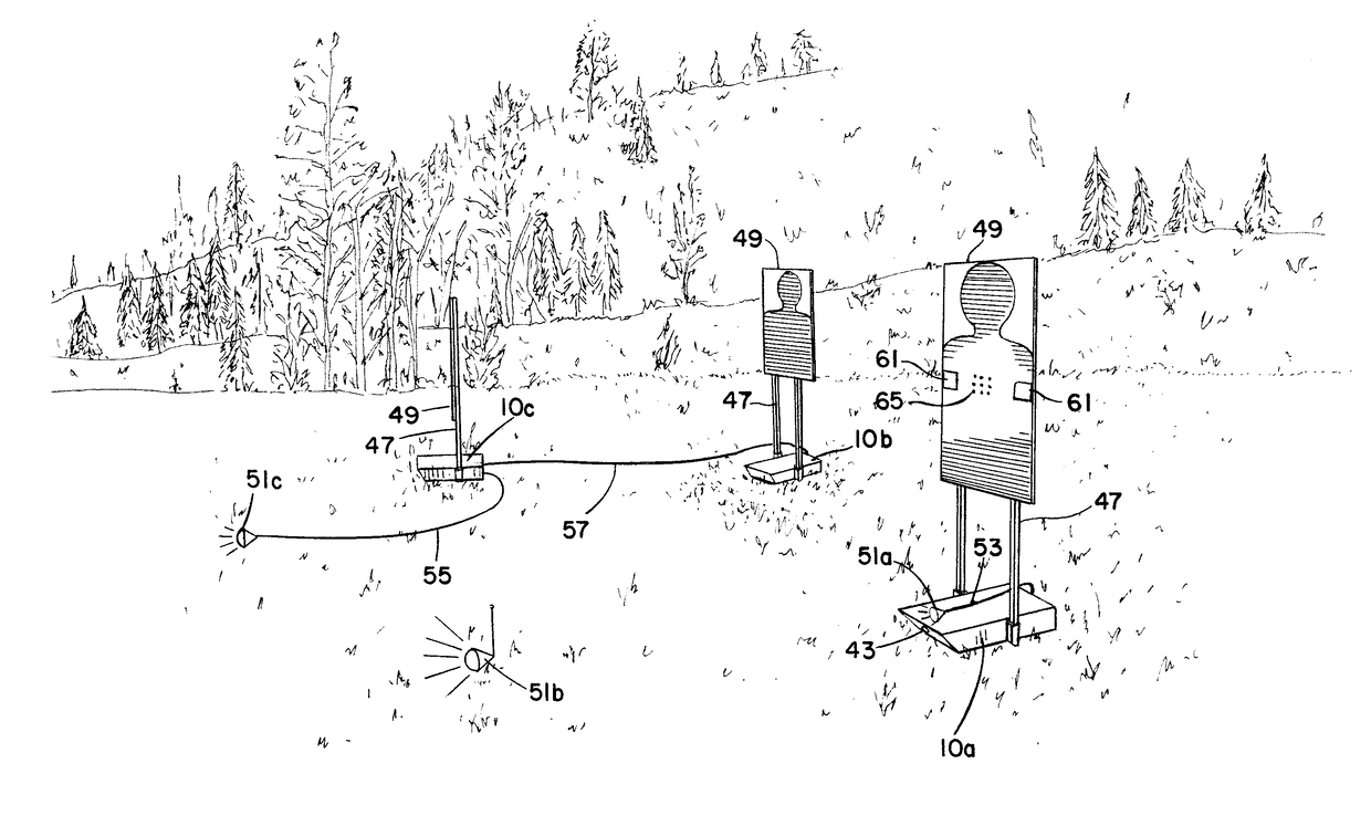
[0026]The following disclosure presents exemplary embodiments for a control module for an autonomous target control system suitable for training military or law enforcement personnel. The module is adapted for use with pop-up targets configured for remote or local activation. The module may be bullet-resistant and designed for deployment in harsh outdoor terrain. A system or method according to the invention automatically deploys targets responsive to triggering signals and automatically conceals targets responsive to hit detection signals. The system may employ centralized or decentralized target control, and can be scaled for controlling any number of targets deployed in a firing range or any other location.

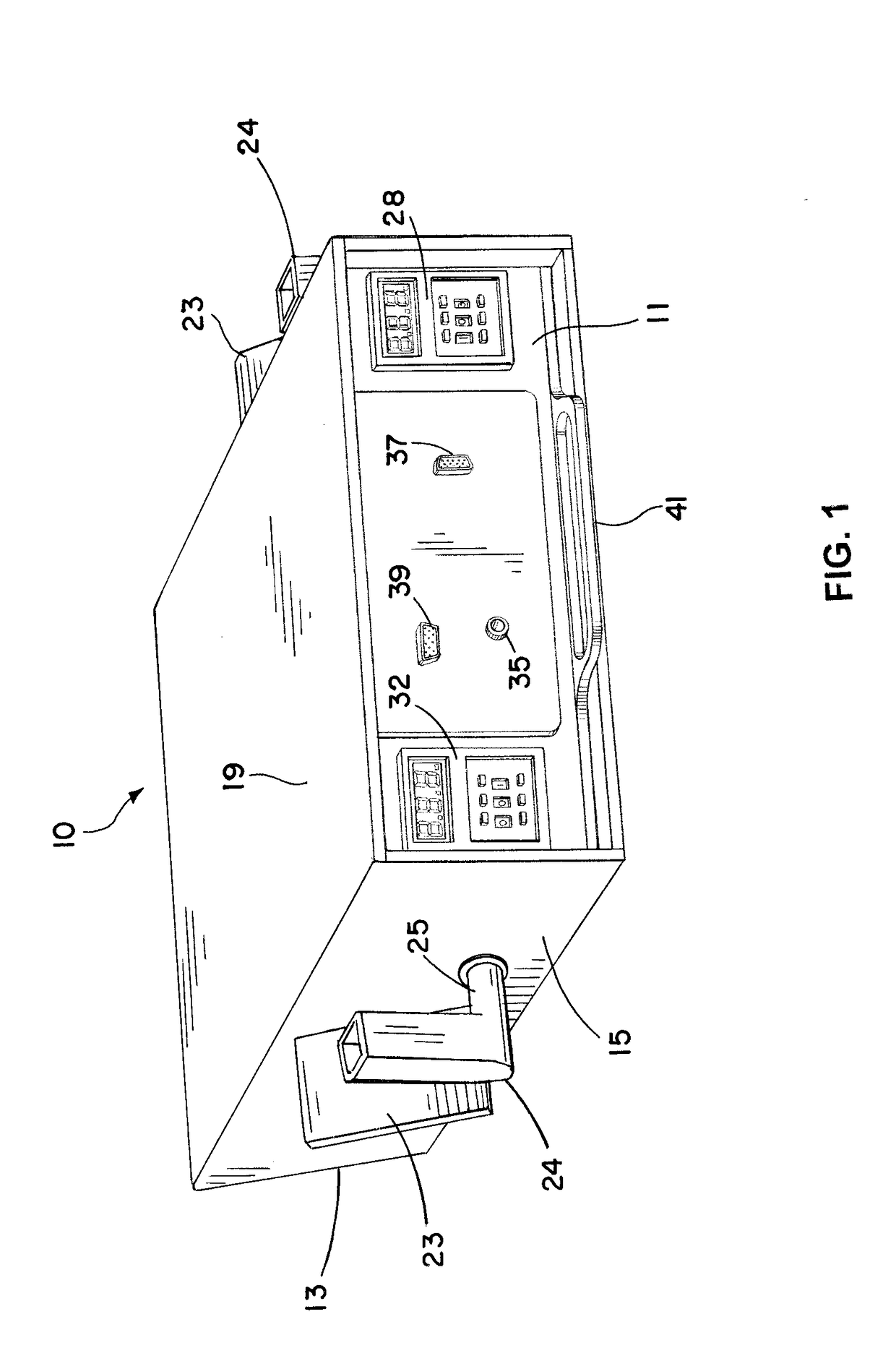
[0027]FIG. 1 shows a rear perspective view of one embodiment of a control module 10 for an autonomous target system according to the present invention. The rear view is provided to better illustrate control features and electrical connections. The chassis of control module 10 c...


PUM


Abstract

A portable control module autonomously positions a target deployed in a combat simulation course. The module chassis is bullet-resistant and angled to deflect errant shots, and encloses a control circuit having an adjustable target exposure delay, an adjustable target exposure duration, means for receiving a trigger signal representing movement of a human body, means for revealing the target when the exposure delay lapses after triggering, means for enabling, only when the target is revealed, hit detection means detecting a shot striking the target, and means for concealing the target responsive to earliest occurrence of the shot detection or lapse of the target exposure duration. The module may include means for relaying the trigger signal to other modules within a cooperative decentralized target control system. A method for the autonomous position control is also disclosed.

Description

BACKGROUND OF THE INVENTION[0001]Field of the Invention[0002]The present invention relates generally to target shooting control systems, to a system and method for controlling multiple autonomous targets, and more specifically to a control module for an autonomous target system which automatically deploys a target responsive to movement of a shooter and automatically conceals a target responsive to hit detection.[0003]Description of Related Art[0004]Target shooting control systems have applications, for example, in the design of pinball machines, shooting galleries, and live firing ranges. Such targeting systems provide dynamic control for positioning one or more targets to reveal or conceal the targets with respect to a shooter's field of view. A common type of target is a pop-up target, which can be toggled by a controller between the “up” or revealed position and the “down” or concealed position. The shooter, whether playing a game or training for live combat, is challenged by th...

Claims


Application Information

Patent Timeline
Patent Type & Authority Applications(United States)
IPC IPC(8): F41J7/06F41J5/18G09B9/00
CPCF41J7/06F41J5/18G09B9/003F41J7/04
Inventor MCFADYEN, MICHAEL D.
Owner ZELL NORMA
Why Eureka
Try Eureka