Annotating Real-World Objects

Active Publication Date: 2017-05-25
DASSAULT SYST SOLIDWORKS CORP
View PDF0 Cites 10 Cited by
  • Summary
  • Abstract
  • Description
  • Claims
  • Application Information

AI Technical Summary

Benefits of technology

[0010]In general, in one aspect, embodiments of the invention feature a computer-implemented method for visualizing a computer-generated annotation in a real-world environment on a computerized system. The method creates a three-dimensional (3D) model of a real-world object. The 3D model is a computer-generated model and can be annotated. The 3D model and the real-world environment are displayed simultaneously on a computer screen, where the 3D model appears within the real-world environment at a specified location and a specified scale. Also simultaneously displayed on the computer screen is a real-world object corresponding to the 3D m

Problems solved by technology

Two-dimensional drawings are often confusing not only because the difficulty some may have mentally constructi

Method used


Image

  • Annotating Real-World Objects
  • Annotating Real-World Objects
  • Annotating Real-World Objects

Examples


Example

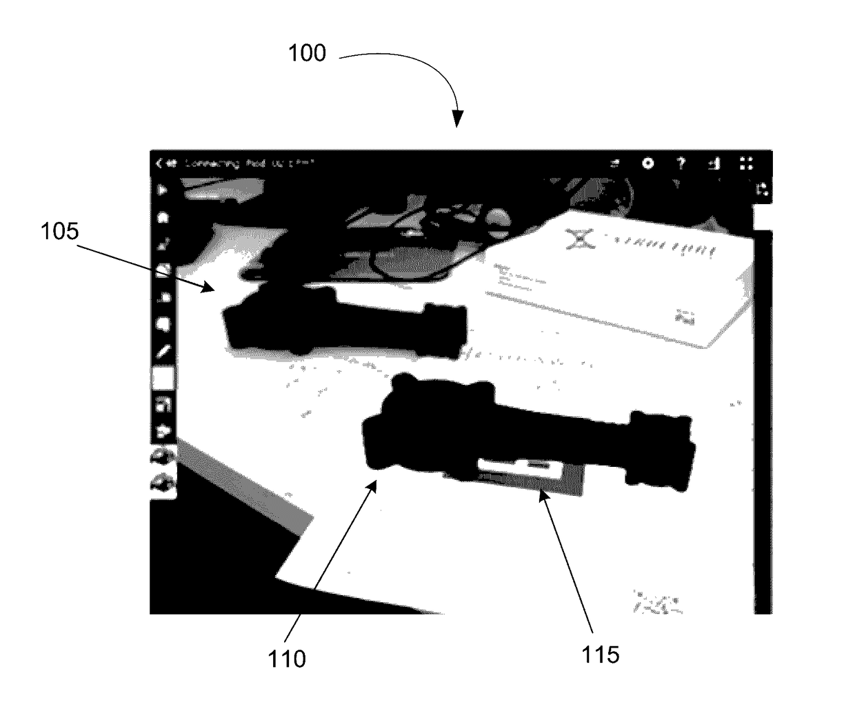
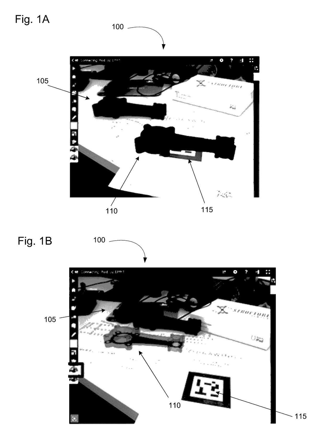
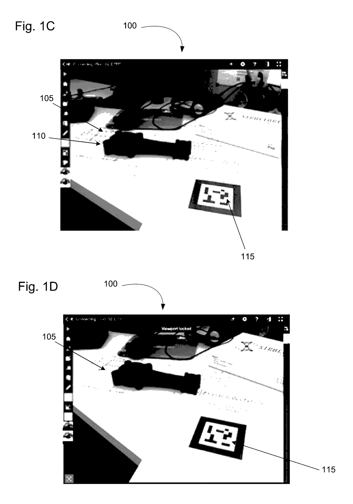
[0022]The present invention enables a user to visualize and author model-based definition (MBD) annotations in a real-world environment. Moreover, the annotations may be displayed on a real-world object. The present invention utilizes augmented reality (AR) viewed through a camera-equipped device (e.g., a tablet, a mobile phone, or wearable AR glasses) to produce an image of a real-world environment. In an embodiment, a real-world object is aligned with a transparent 3D model of the object. The user may reference the underlying geometry (including faces, edges, and vertices), and MBD features (such as holes, bosses, fillets, chamfers, cuts, shells, lofts, and sweeps), to review and annotate the model in a real-world environment. As a result, a user has the ability to (a) view MBD dimensions and tolerances on a real-world object in a real-world environment, (b) query model dimensions and tolerances and display the dimensions and tolerances on the real-world object, (c) use the real-w...


PUM


Abstract

A computer-implemented method and system enables visualization of a computer-generated annotation on a real-world object in a real-world environment on a computerized system. The method and system creates a three-dimensional (3D) model of the real-world object, simultaneously displays the 3D model, the real-world object, and the real-world environment on a computer screen, and aligns the displayed 3D model and the displayed real-world object. The visibility of the 3D model is reduced and the 3D model is annotated in a real-world context. Reducing the visibility of the 3D model causes the annotation to appear on the displayed real-world object.

Description

BACKGROUND OF THE INVENTION[0001]Computer-aided design (CAD) software allows a user to construct and manipulate complex three-dimensional (3D) models. A number of different modeling techniques can be used to create a 3D model. One such technique is a solid modeling technique, which provides for topological 3D models where the 3D model is a collection of interconnected topological entities (e.g., vertices, edges, and faces). The topological entities have corresponding supporting geometrical entities (e.g., points, trimmed curves, and trimmed surfaces). The trimmed surfaces correspond to topological faces bounded by edges. Hereinafter, the terms vertex, edge, and face will be used interchangeably with their respective, corresponding geometric entities.[0002]A design engineer is a typical user of a 3D CAD system. The design engineer designs physical and aesthetic aspects of 3D models, and is skilled in 3D modeling techniques. The design engineer creates parts and may assemble the parts...

Claims


Application Information

Patent Timeline
IPC IPC(8): G06F17/50G06T19/20
CPCG06T19/20G06F17/50G06T19/006G06T2219/004G06T2219/012G06F30/00G06F30/17
Inventor REEVES, BLAKEHASAN, ERICLORONO, MATTHEW
Owner DASSAULT SYST SOLIDWORKS CORP
Why Eureka
Try Eureka