Switch module with a built-in structure of Anti-surge and dual disconnection

a technology of anti-surge and built-in structure, which is applied in the direction of protective switch operation/release mechanism, contact fixed to the operating part, tumbler/rocker switch details, etc., can solve the problems of circuit may still be working, circuit may not be completely disconnected, and may not be able to protect the device, so as to achieve more electricity safety and convenience in use.

Inactive Publication Date: 2017-05-25
WANG YI HSIANG +1
View PDF1 Cites 13 Cited by
  • Summary
  • Abstract
  • Description
  • Claims
  • Application Information

AI Technical Summary

Benefits of technology

[0014]Another object of the present invention is to ensure a complete disconnection even when conductive plates fail to disconnect a circuit within the switch.
[0019]With structures disclosed above, the present invention complements the defect of a conventional overcurrent protection switch that it has to connect to a metal oxide varistor from the outside by having the anti-surge disconnection structure ingeniously built inside the heat-resisting and fireproof housing. When receiving exceedingly high voltages, the heating metal oxide varistor would instantly melt down the thermo-sensitive piece, loosening the springy section of the conductive spring element for ejection and further displacing the pushing element, therefore forcing the first connecting point detaching from the second connecting point and turning off the switch immediately. Therefore, the present invention is not only overcurrent protective but also overvoltage protective and surge absorbing; also, the insulating element is able to completely disconnect the thermo-sensitive piece and the spring element from the metal oxide varistor by insulation, ensuring more electricity safety and conveniences in using.

Problems solved by technology

However, the structure disclosed above aims at protection from overcurrent situation but is not able to protect the device when sudden overvoltage such as lightning strike occurs.
However, both inventions can only disconnect the circuit of series connection, but cannot ensure the structure therein is completely disconnected.
That is, the outer periphery of the spring element would still contacting surfaces of the metal oxide varistor; and if the entire structure cannot be disconnected thoroughly, the circuit may still be working and keep heating up, resulting in a dangerous situation.
On the other hand, metal oxide varistors are prone to operate function less effectively after in use for a period.

Method used


Image

  • Switch module with a built-in structure of Anti-surge and dual disconnection
  • Switch module with a built-in structure of Anti-surge and dual disconnection
  • Switch module with a built-in structure of Anti-surge and dual disconnection

Examples


first embodiment

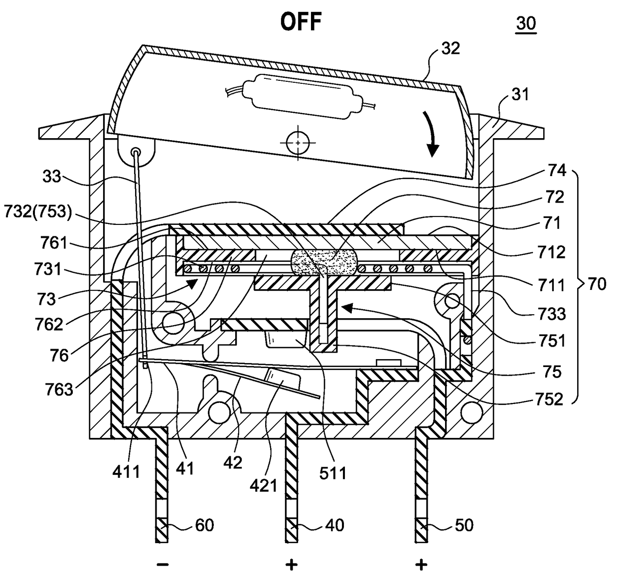
[0037]Referring to FIGS. 3-6, in a first embodiment, the present invention mainly includes a housing 31, a moving rod 33, and an anti-surge disconnection structure 70.

[0038]The housing 31 has a press button 32 arranged atop thereof, and a first conductive plate 40 as a positive electrode, a second conductive plate 50 as another positive electrode and a third conductive plate 60 as a negative electrode arranged at a lower section thereof. The first conductive plate 40 is connected to a binary alloy conductive plate 41 that has a spring leaf 42 and a first connecting point 421, and the second conductive plate 50 has a second connecting point 511 corresponding to the first connecting point 421.

[0039]The moving rod 33 has a top end arranged at the bottom of the press button 32 and a bottom end connecting to a movable end 411 of the binary alloy conductive plate 41. With reference to FIG. 4, when pressing the press button 32, the binary alloy conductive plate 41 ejects upwards and the sp...

second embodiment

[0049]FIGS. 7-9 illustrate elements of the present invention in a In this embodiment, the anti-surge disconnection structure 70 mainly comprises a first metal oxide varistor 71a, a second metal oxide varistor 71b, a first thermo-sensitive piece 72a, a second thermo-sensitive piece 72b, a first insulating element 76a, a second insulating element 76b, a conductive spring element 73a, an electrical connector 73c, and a pushing element 75.

[0050]The first metal oxide varistor 71a is disposed under a plate 74 and has a first surface 711 and an opposite second surface 712. The first insulating element 76a has a through hole 763 arranged at a center thereof, an upper surface 761 and a lower surface 762. The spring element 73a has an a springy section 732 compressed in the through hole 763 by the first surface 711 of the first metal oxide varistor 71a and an outer periphery 731 having a first extended portion 733a connecting to the first surface 711 of the first metal oxide varistor 73a wit...

third embodiment

[0054]FIGS. 10-12 illustrate the present invention. In this embodiment, the anti-surge disconnection structure 70 mainly comprises a first metal oxide varistor 71a, a second metal oxide varistor 71b, a third metal oxide varistor 71c, a first thermo-sensitive piece 72a, a second thermo-sensitive piece 72b, a third thermo-sensitive piece 72c, a first insulating element 76a, a second insulating element 76b, a third insulating element 76c, a first spring element 73a, a second spring element 73b, an electrical connector 73c and a pushing element 75.

[0055]The first insulating element 76a has a through hole 763 arranged at a center thereof, an upper surface 761 and a lower surface 762. The upper surface 761 is arranged correspondingly to the first surface 711 of the first metal oxide varistor 71a. The first thermo-sensitive piece 72a is conductive and solid colloid to be disposed in the through hole 763 of the first insulating element 76a for a springy section 732 of the first spring eleme...


PUM


Abstract

A switch module with a built-in structure of anti-surge and dual disconnection mainly comprises an overcurrent protection switch having plates and insulating elements for anti-surge and dual disconnection structure ingeniously built inside a heat-resisting housing. The switch module has a first connecting point and a second connecting point for operation. When overvoltage occurs, temperature of at least one metal oxide varistor would instantly rise up to a degree higher than the melting point thereof, melting at least one thermo-sensitive piece, loosening at least one spring element, displacing a pushing element and thus forcing the connecting points detaching from each other to turn off the switch and stop supplying electricity power; meanwhile, insulating elements would isolate conductive components such as thermo-sensitive pieces, spring elements and plates to further ensure a complete disconnection and more of electricity safety.

Description

[0001]This patent application is a continuation-in-part of Ser. No. 14 / 950,069 filed on Nov. 24, 2015, currently pending.BACKGROUND OF THE INVENTION[0002]1. Field of the Invention[0003]The present invention relates to a switch module with a built-in structure of anti-surge and dual disconnection, particularly to one that has conductive plates disconnecting a series connection and an anti-surge structure disconnecting a parallel connection by insulation elements.[0004]2. Description of the Related Art[0005]FIGS. 1A and 1B disclose a conventional overcurrent protection switch 10 that has plural connecting points arranged in the middle part and comprises a housing 11 with a press button 12 on the top, a first terminal 12a, a second terminal 12b, a third terminal 12c separately arranged at the bottom, and a moving element 14. The first terminal 12a has a bimetal plate 13 and a first contact 131; the second terminal 12b has a second contact 121 corresponding to the first contact 131. The...

Claims


Application Information

Patent Timeline
Patent Type & Authority Applications(United States)
IPC IPC(8): H01H89/04
CPCH01H89/04H01H2235/028H01H2205/002H01H37/761H01H71/20H01H83/10H01H9/0271H01H23/20
Inventor WANG, YI-HSIANGWANG, I-YING
Owner WANG YI HSIANG
Why Eureka
Try Eureka