
Pipette for activating a syringe

a technology for actuating syringes and pipettes, which is applied in the direction of laboratory glassware, chemistry apparatus and processes, laboratory apparatus, etc., can solve the problems of lack of adjustment options and total unnecessary adjustmen

Active Publication Date: 2017-06-01
EPPENDORF SE
View PDF11 Cites 8 Cited by
  • Summary
  • Abstract
  • Description
  • Claims
  • Application Information

AI Technical Summary

Benefits of technology

The invention is about a new device for adjusting a cam in a toothed rack. The device is designed to ensure that the cam is positioned correctly for optimal dropping of a pawl in the teeth of the rack. The device uses a plastic cover that is over-molded to achieve precise distances between the coupling element and catching edge, and catching edge and bend. The cover is securely connected to the toothed rack, and the cam is adjustable in an axial direction. The technical effects of the invention include improved accuracy and efficiency in adjusting the cam, and improved performance of the toothed rack.

Problems solved by technology

Later readjustments have proven to be entirely unnecessary, and the lack of adjustment options is, therefore, not a disadvantage.

Method used


Image

  • Pipette for activating a syringe
  • Pipette for activating a syringe
  • Pipette for activating a syringe

Examples


Embodiment Construction

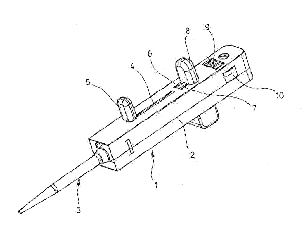
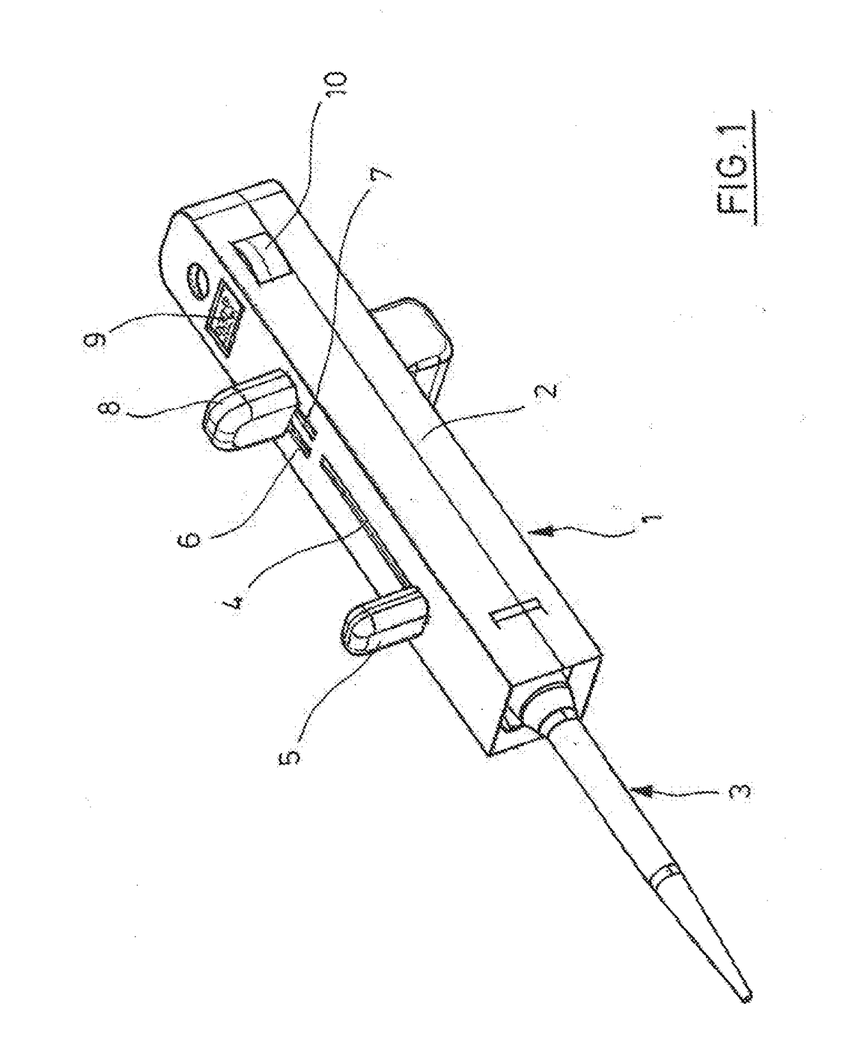
[0077]According to FIG. 1, a pipette 1 has a rod-shaped housing 2 in which a syringe 3 is held at the bottom. A drawing lever 5 projects from the housing 2 from a sidewall of the housing 2 over a straight slot 4. A control knob 8 of a toothed rack and pawl control projects from the same side wall of the housing 2 above two additional slots 6, 7. Above that, a display apparatus in the form of a display 9 is recessed in the same side wall of the housing 2. Segments of a selection wheel 10 project from openings in the adjacent sidewall.

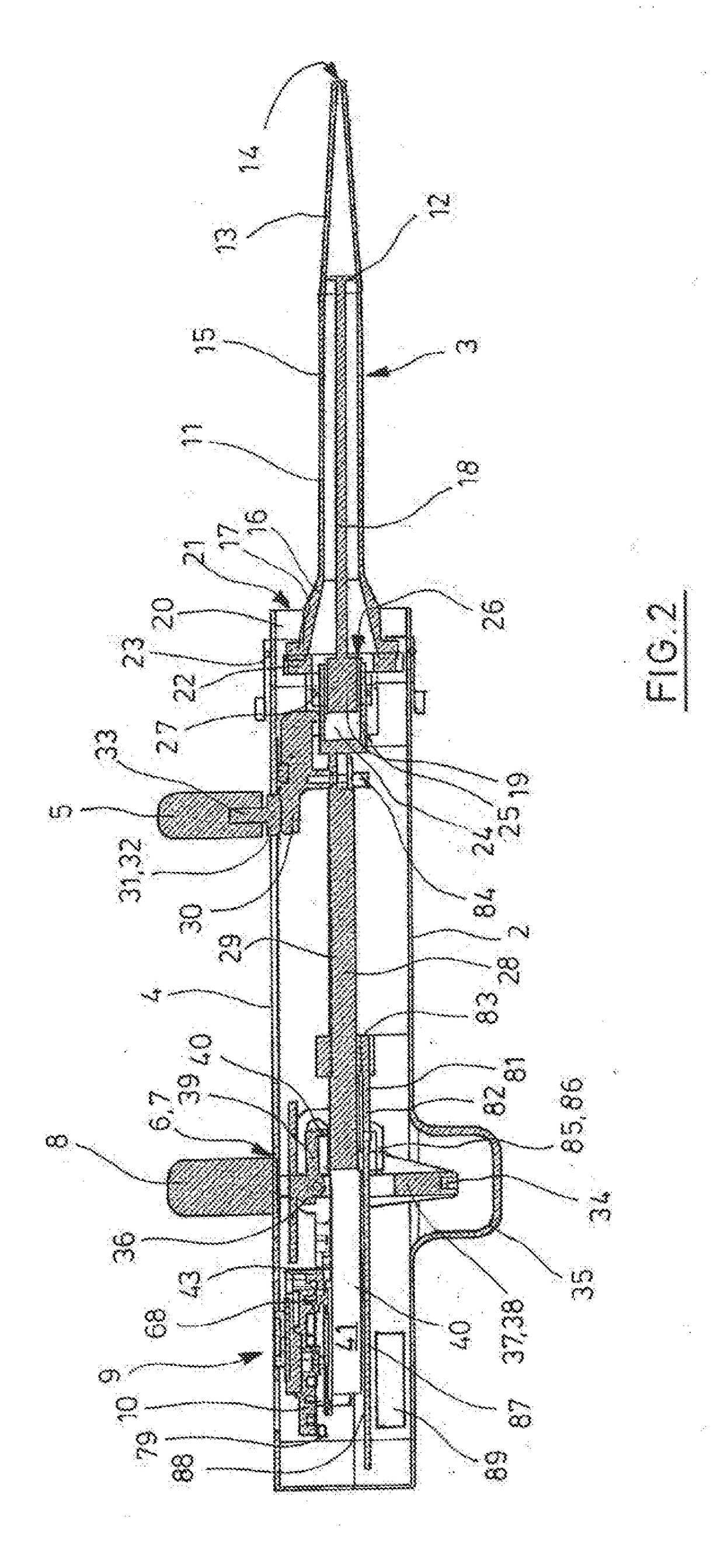
[0078]According to FIG. 2, the syringe 3 has a cylinder 11 and a plunger 12 movably arranged therein. The cylinder 11 has a conical section 13 at the bottom with a hole 14 for the passage of liquids, and a cylindrical section 15 above that in which the plunger 12 can be displaced. At the top, the cylinder 11 has a first fastening section 16 with a peripheral flange 17. From the plunger 12, a plunger rod 18 projects upward and has a second fastening secti...


PUM


Abstract

A pipette for actuating a syringe including a strip-shaped housing with first and second receptacles for inserting fastening sections. First and second releasable holding mechanism for holding the fastening sections. First and second displacing mechanisms to displace a receiving body in the housing from the receptacles. A toothed rack and a pawl are connected to an actuation rack. A cover has a coupling element and longitudinal slot and spring.

Description

FIELD OF THE INVENTION[0001]The invention relates to a pipette for actuating a syringe.BACKGROUND OF INVENTION[0002]The pipettes at issue here for actuating a syringe serve to dispense the liquid drawn into the syringe in several steps. They are also termed dispensers or repeating pipettes. At the bottom end of a rod-shaped housing, these pipettes have a receptacle for a flange of a syringe cylinder and, in the housing, have a displaceably receiving body with a plunger receptacle for the top end region of a plunger rod of a syringe plunger. The syringe can be inserted with the flange and the end region of the plunger rod through axially-aligned openings in the receptacles. The flange and the end region are held in the receptacles by means for releasably holding that, for example, are designed as spring-loaded grip levers. Furthermore, the pipette has means for displacing the receiving body that make it possible to partially remove the plunger from the cylinder to draw liquid into th...

Claims


Application Information

Patent Timeline
Patent Type & Authority Applications(United States)
IPC IPC(8): B01L3/02
CPCB01L3/0234B01L2200/12B01L2200/025
Inventor WILTH, MARCREICHMUTH, BURKHARDTSATTLER, JORG
Owner EPPENDORF SE
Learn More