Control device, robot, and robot system

a control device and robot technology, applied in the field of control devices, robots, and robot systems, can solve the problems of long time in determining the position and the posture of the calibration tool, difficult to perform high-accuracy calibration, and the inability to accurately perform various types of work. to achieve the effect of accurate performing various types of work

Active Publication Date: 2017-06-01
SEIKO EPSON CORP
View PDF2 Cites 24 Cited by
  • Summary
  • Abstract
  • Description
  • Claims
  • Application Information

AI Technical Summary

Benefits of technology

[0036]According to the robot system, the robot can accurately perform v

Problems solved by technology

Therefore, it is difficult to determine the position and the posture of the calibration tool with high accuracy.
In addition, there is a problem that it takes a long period of time in determining the position and the posture

Method used


Image

  • Control device, robot, and robot system
  • Control device, robot, and robot system
  • Control device, robot, and robot system

Examples


first embodiment

Robot System

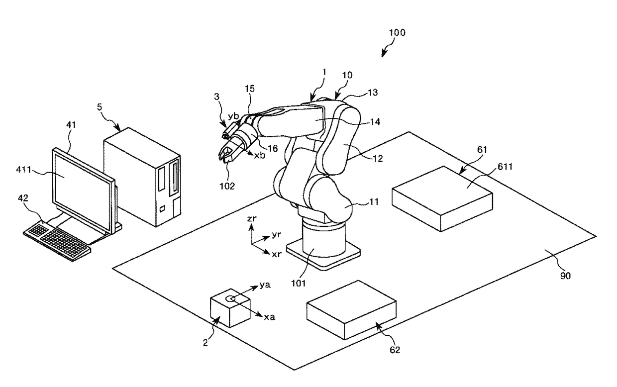
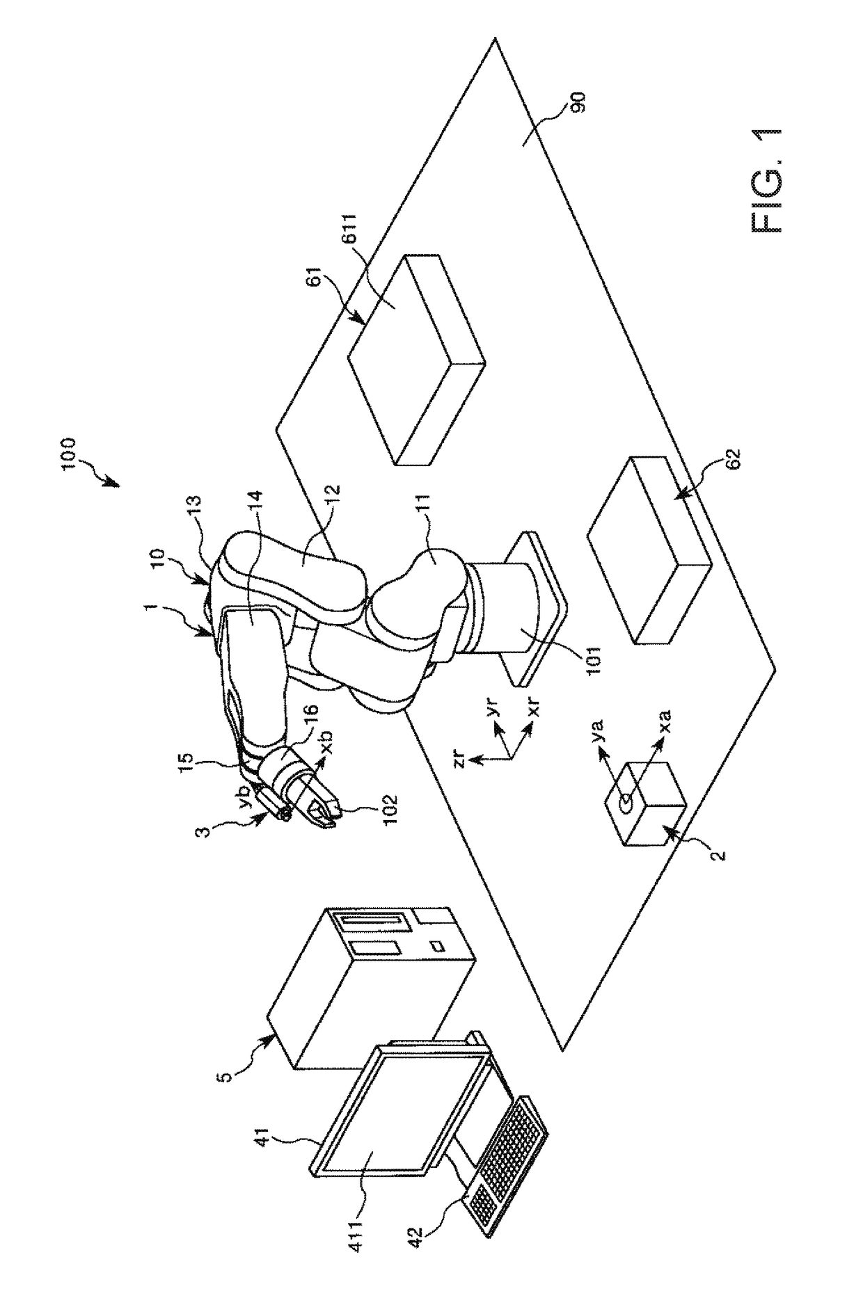
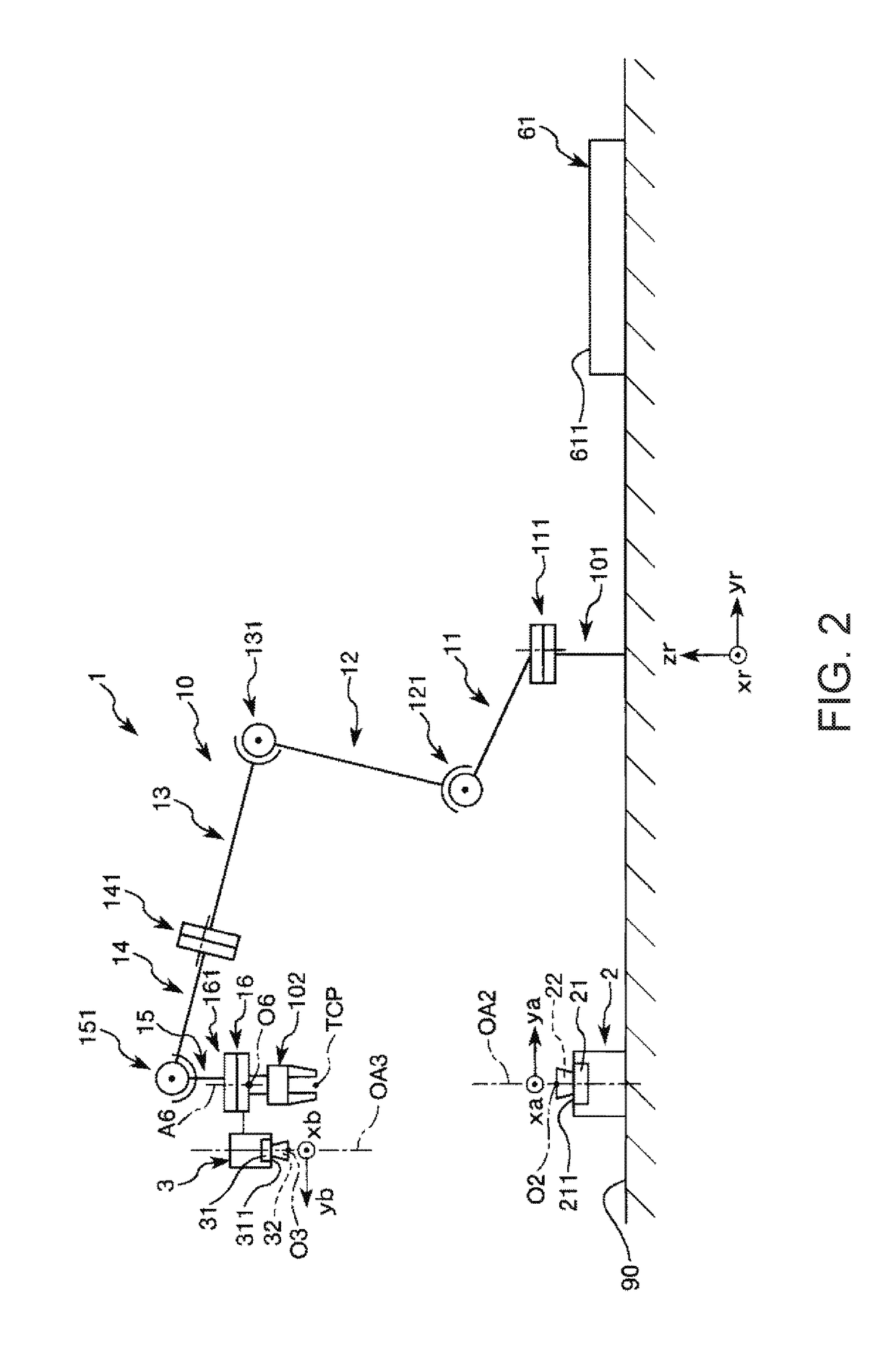
[0063]FIG. 1 is a schematically perspective view illustrating the robot system according to a first embodiment of the invention. FIG. 2 is a schematic view of the robot illustrated in FIG. 1. FIG. 3 is a block diagram of the robot system illustrated in FIG. 1.

[0064]In addition, hereinafter, for convenience of the description, an upper side in FIG. 2 is referred to as “up” or “upper part”, and a lower side is referred to as “down” or “lower part”. In addition, the upward-and-downward direction in FIG. 2 is referred to as “vertical direction”, a surface which intersects the vertical direction is referred to as “horizontal surface”, and the direction parallel to the horizontal surface is referred to as “horizontal direction”. Here, “horizontal” described in the specification also includes a case of being inclined within a range of equal to or less than 5° with respect to a horizontal state not being limited to being completely horizontal. In addition, “vertical” described i...

second embodiment

[0211]Next, a second embodiment of the invention will be described.

[0212]FIG. 22 is a plan view of the calibration member which is used in calibrating the imaging portion that uses the robot system according to the second embodiment of the invention. FIG. 23 is a view illustrating comparison of the first marker with the n-th marker in the processing of determining the reference surface in the second embodiment.

[0213]The calibration method of the imaging portion which uses the robot system according to the embodiment is similar to the above-described first embodiment except that the configuration of the calibration member and a part of the processing of determining the reference surface are different.

[0214]In addition, in the following description, regarding the second embodiment, the description will focus on the difference from the above-described embodiment, and the description of similar parts will be omitted. In addition, in FIGS. 22 and 23, configurations similar to those of th...

third embodiment

[0229]Next, a third embodiment of the present invention will be described.

[0230]FIG. 24 is a plan view of the calibration member which is used in calibrating the imaging portion that uses the robot system according to the third embodiment of the invention.

[0231]The calibration method of the imaging portion which uses the robot system according to the embodiment is similar to that of the above-described first embodiment except that the configuration of the calibration member is different.

[0232]In addition, in the following description, regarding the third embodiment, the description will focus on the difference from the above-described embodiment, and the description of similar parts will be omitted. In addition, in FIG. 24, configurations similar to the above-described embodiment will be given the same reference numeral.

[0233]A first marker 71B, a second marker 72B, and a third marker 73B are attached to a front surface 701B of a calibration member 70B illustrated in FIG. 24.

[0234]B...


PUM


Abstract

A control device is capable of controlling each of a robot having a robot arm, and an imaging portion which is capable of capturing a first reference marker, a second reference marker, and a third reference marker, any one of the imaging portion, the first reference marker, the second reference marker, and the third reference marker is provided in the robot, and a posture of a reference surface parallel to a plane which passes through the first reference marker, the second reference marker, and the third reference marker, is acquired based on a first image in which the first reference marker is captured by the imaging portion, a second image in which the second reference marker is captured by the imaging portion, and a third image which captures the third reference marker by the imaging portion.

Description

BACKGROUND[0001]1. Technical Field[0002]The present invention relates to a control device, a robot, and a robot system.[0003]2. Related Art[0004]From the related art, a robot system which is used in work of gripping, transporting, and assembling a target, such as an electronic component, is known. The robot system includes: a robot including a robot arm having a plurality of arms, and a hand provided at a tip end thereof; an imaging portion, such as a camera; and a control device which controls each of the robot and the imaging portion. In a robot system having such a configuration, for example, the robot performs various types of work with respect to the target with the hand based on an image of the target captured by the imaging portion.[0005]Here, it is necessary to calibrate the imaging portion which acquires a correction parameter for converting a position and a posture on the image of the target captured by the imaging portion into a value in a robot coordinate system so that ...

Claims


Application Information

Patent Timeline
IPC IPC(8): B25J9/16G06K9/78G06K9/64G06K9/00
CPCB25J9/1692G06K9/00355B25J9/1697G06K9/64G06K9/78B25J9/16B25J19/00G06T2207/30108G06T2207/30208G06T7/80G06V10/10G06V10/75G06V40/28
Inventor ISHIGE, TAROHARADA, ATSUSHIYAMAGUCHI, YUKIHIROABE, HIROMITSU
Owner SEIKO EPSON CORP
Why Eureka
Try Eureka