
Fuel Injector for an Internal Combustion Engine

Inactive Publication Date: 2017-06-01
DELPHI TECH IP LTD
View PDF2 Cites 2 Cited by
  • Summary
  • Abstract
  • Description
  • Claims
  • Application Information

AI Technical Summary

Benefits of technology

The patent is about a device that controls the pressure in a chamber by allowing or hindering the flow of fuel. The device has two orifices that allow fuel to flow out of the chamber at different rates, depending on the temperature. This design helps to reduce the pressure in the control chamber, making it easier to open the nozzle.

Problems solved by technology

However, it has been observed that the injector performances are altered at low temperatures, e.g. when starting a cold engine under cold climate conditions, say below 0° C. This appears to be mostly due to the fact that at low temperatures, the viscosity of the fuel increases substantially, causing difficulties for opening the nozzle and thus deficiency on the injector delivery rate.

Method used


Image

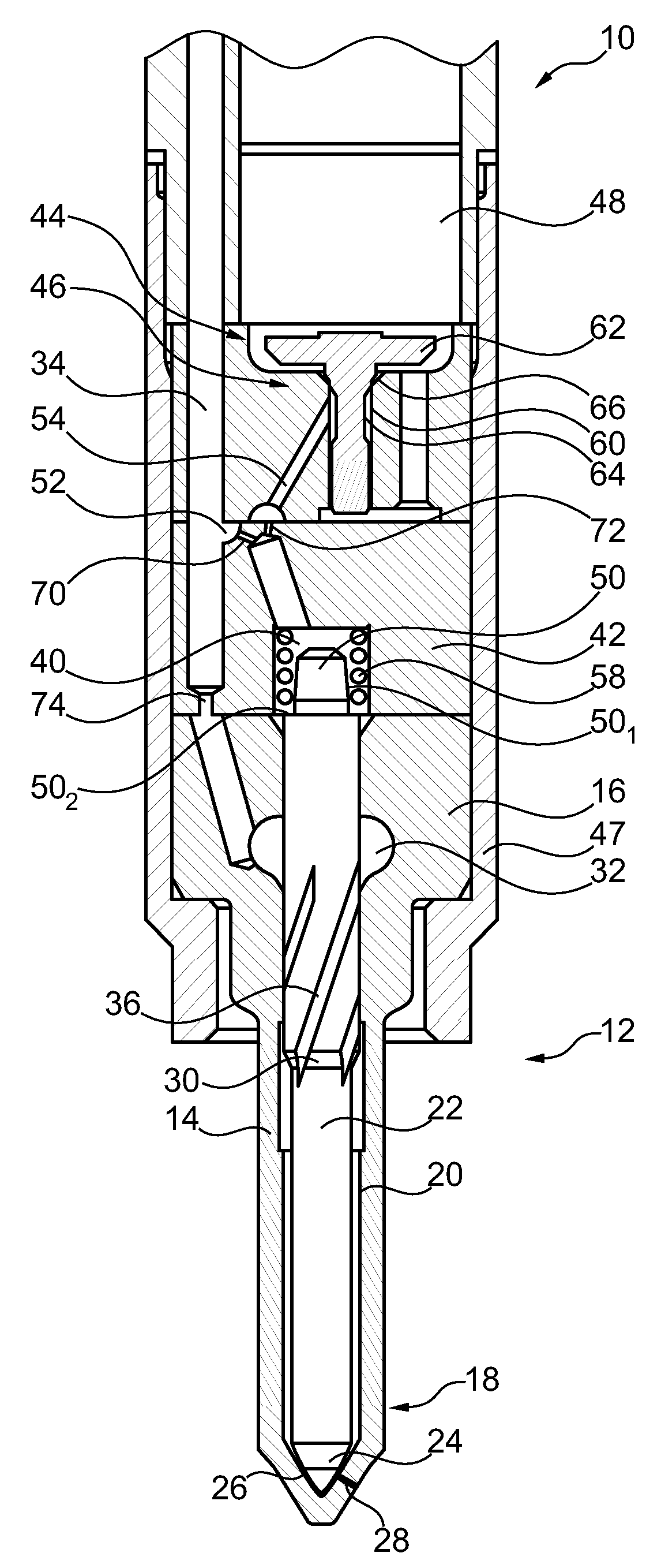
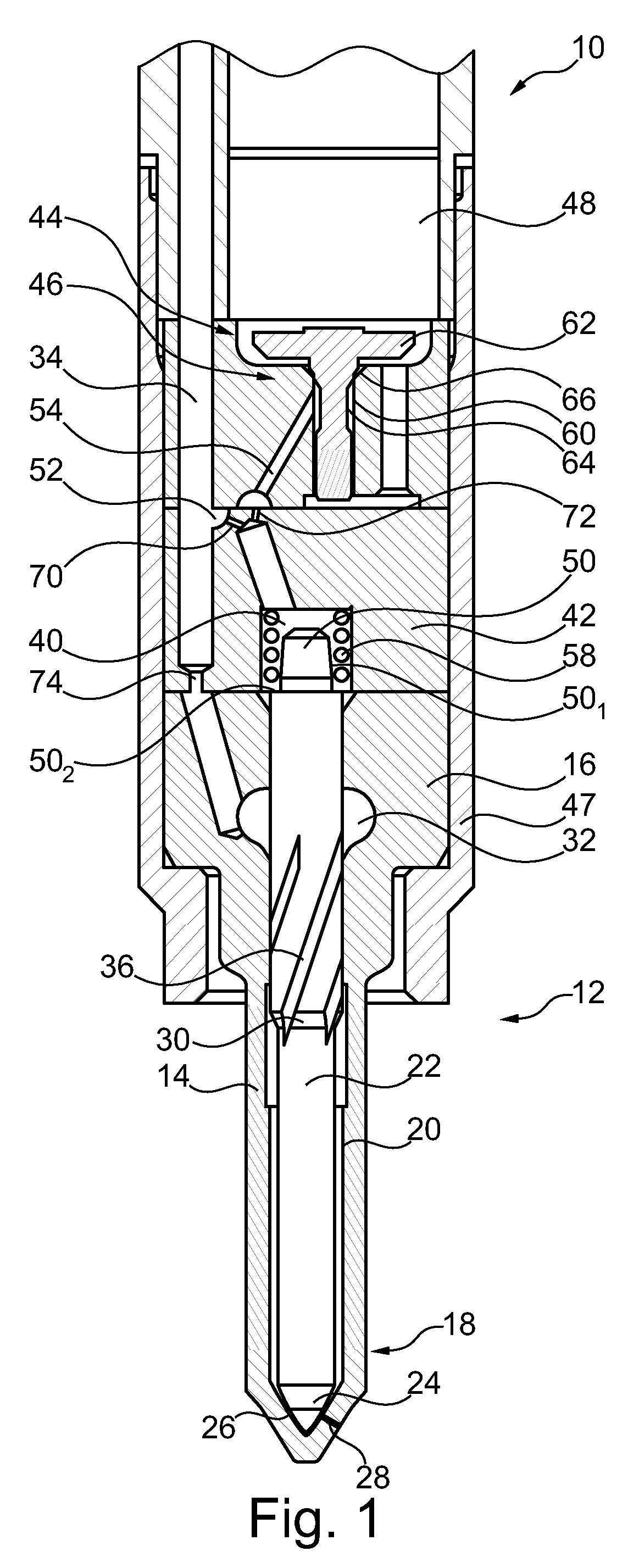
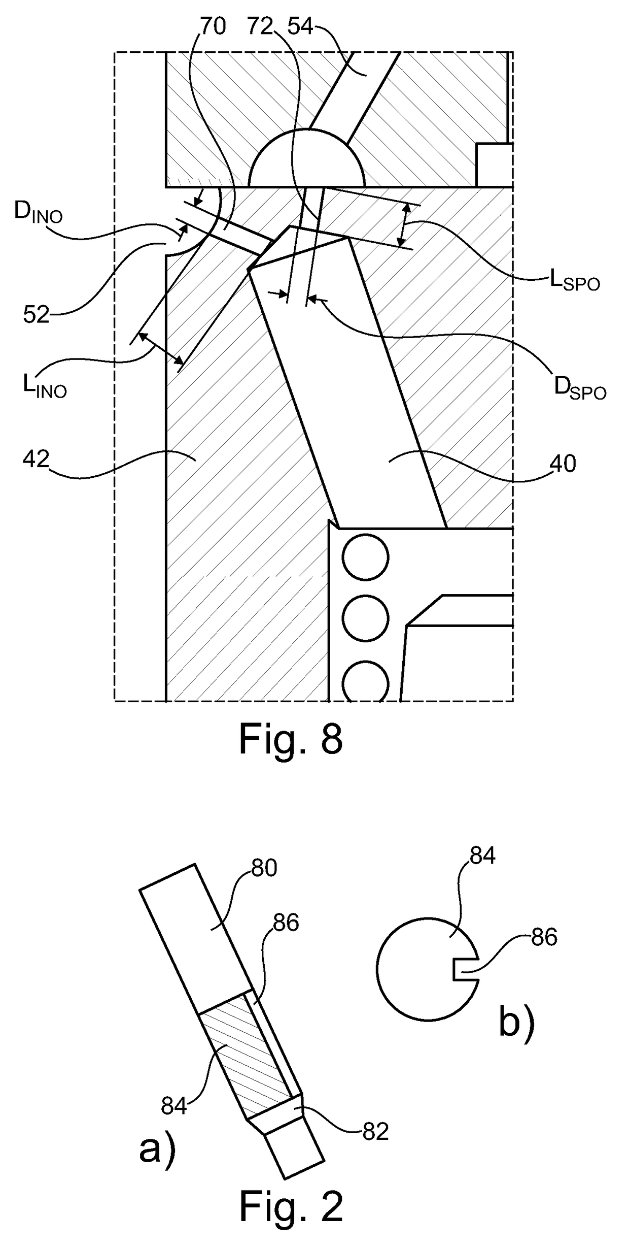
  • Fuel Injector for an Internal Combustion Engine
  • Fuel Injector for an Internal Combustion Engine
  • Fuel Injector for an Internal Combustion Engine

Examples


example

[0059]An example of the efficiency of the present injector will now be given in the following.

[0060]In Table 1, summarizes the dimensional properties of the inlet and outlet orifices of two injectors according to the present design, noted A and B. Injector Z is a comparative example with a Rdim not falling in the above prescribed range.

[0061]All three injectors have otherwise the same configuration. Since the dimensions of the outlet orifices are the same, and DINO substantially similar, the only sensibly varying parameter is thus LINO.

TABLE 1InjectorABZLINO2.50 mm 1.20 mm 0.7 mmDINO0.2622 mm 0.257 mm0.256 mmLSPO 0.7 mm 0.7 mm 0.7 mmDSPO0.221 mm 0.221 mm0.221 mmRdim0.330.681.16

[0062]FIGS. 3 to 7 illustrate some performances of injectors A, B and Z. FIGS. 3 to 6 correspond to the following test conditions: −20° C., 3500 μs pulse and 300b rail pressure. Turning first to FIG. 3, a reduction in the flow rate through the inlet opening INO with decreasing Rdim can be clearly observed. Inj...


PUM


Abstract

A fuel injector includes a nozzle body having a spray tip with at least one spray orifice and a needle slideably arranged in the nozzle body in order to control the spray orifice. A control chamber is associated with the needle, which is filled with high-pressure fuel in order to exert a pressure force on the needle in its closing direction; the control chamber being in communication with a high pressure fuel channel through an inlet restrictor and with a low pressure drain through an outlet restrictor via a control valve to selectively allow or hinder the flow of fuel out of the control chamber through the outlet restrictor. The inlet restrictor and outlet restrictor are designed so that the ratio of outlet fuel flow rate over inlet fuel flow rate increases at low fuel temperatures, in order to cause a greater pressure reduction in the control chamber.

Description

FIELD OF THE INVENTION[0001]The present invention generally relates to the field of internal combustion engines and more specifically to a fuel injector for such engine, in particular for a diesel engine.BACKGROUND OF THE INVENTION[0002]As it is well known in the art, a fuel injection system of an internal combustion engines typically includes a plurality of fuel injectors, each of which is arranged to inject fuel into the combustion chamber of an associated engine cylinder. Each fuel injector is supplied with high-pressure fuel from a suitable source, such as a common rail, which is charged with fuel at high pressure by a high-pressure fuel pump.[0003]A fuel injector generally comprises a nozzle body, which houses an elongate valve needle. The nozzle body has a spray tip with one or more spray orifices, and, in use, the injector is mounted so that its spray tip protrudes into the associated combustion chamber, whereby fuel can be injected into the combustion chamber at high pressur...

Claims


Application Information

Patent Timeline
IPC IPC(8): F02M47/02
CPCF02M2200/28F02M47/02
Inventor RODIER, NICOLASROUSSOT, QUENTIN
Owner DELPHI TECH IP LTD
Learn More