Unlock instant, AI-driven research and patent intelligence for your innovation.

Flex shaft

a technology of flex shafts and shafts, applied in the direction of couplings, mechanical equipment, drilling pipes, etc., can solve the problems of inability to meet the requirements of flex shafts, drive shafts may be too long, etc., and achieve the effect of shortening the overall length and achieving the desired level of flexibility

Inactive Publication Date: 2017-06-08
MS DIRECTIONAL LLC
View PDF14 Cites 5 Cited by
  • Summary
  • Abstract
  • Description
  • Claims
  • Application Information

AI Technical Summary

Benefits of technology

The patent describes a flexible shaft for a motor that is made up of a hollow tubular member with openings in its wall for flexibility. The openings can be arranged in different ways, and the shaft allows for a shorter overall length compared to a solid shaft. The technical effect of this design is that it provides a lightweight, flexible shaft that can handle high levels of torque.

Problems solved by technology

One of the difficulty with flexible drive shafts is that the diameter of the drive shaft may be selected in accordance with a desired strength, whereas the length is selected in accordance with a desired flexibility.
However, in some cases, the resulting drive shaft may be too long or impractical.

Method used


Image

  • Flex shaft
  • Flex shaft
  • Flex shaft

Examples


Embodiment Construction

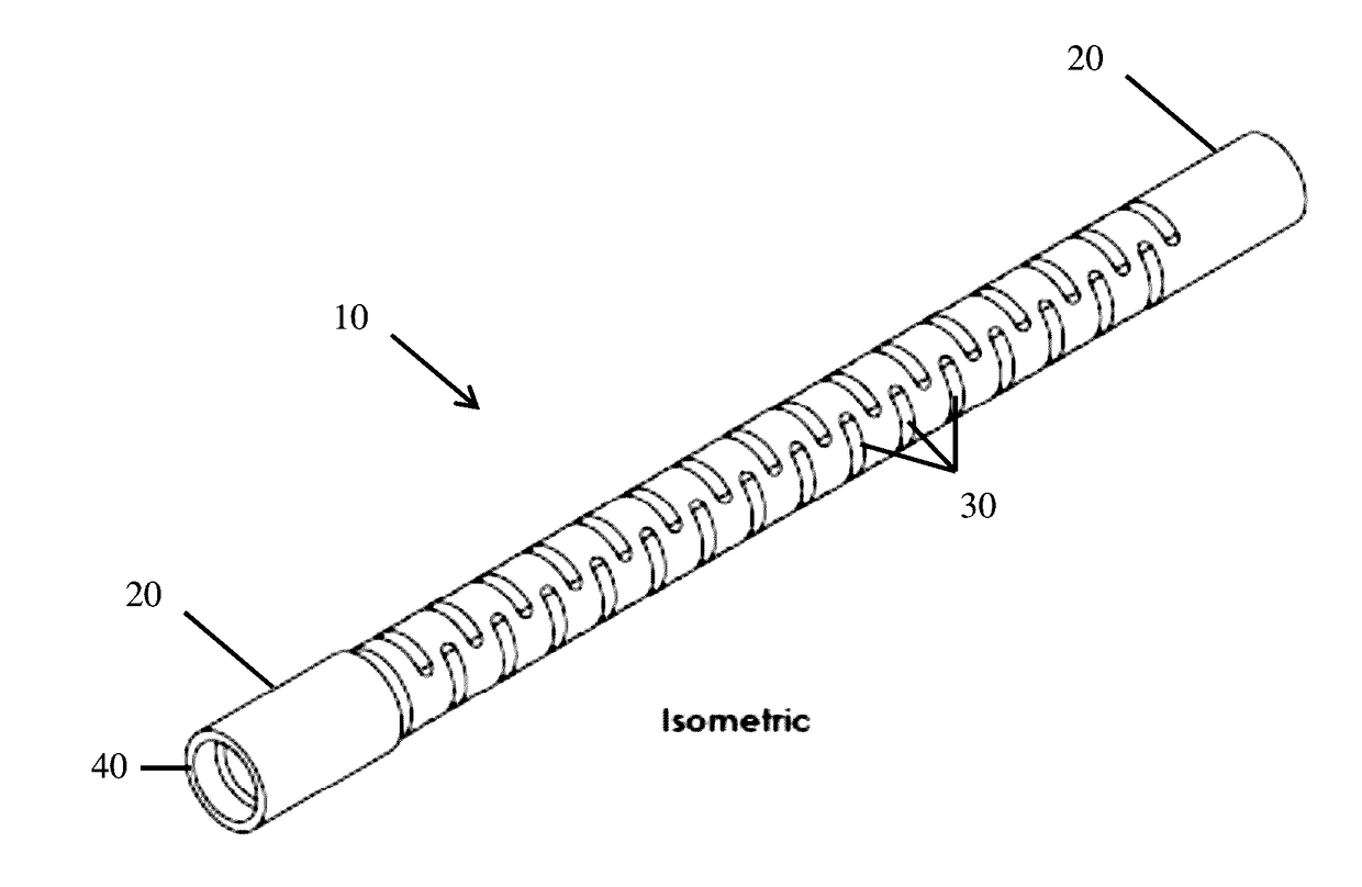
[0009]Refer now to the drawings wherein depicted elements are not necessarily shown to scale and wherein like or similar elements are designated by the same reference numeral through the several views.

[0010]Referring to the drawings in general, it will be understood that the illustrations are for the purpose of describing particular implementations of the disclosure and are not intended to be limiting thereto. While most of the terms used herein will be recognizable to those of ordinary skill in the art, it should be understood that when not explicitly defined, terms should be interpreted as adopting a meaning presently accepted by those of ordinary skill in the art.

[0011]It is to be understood that both the foregoing general description and the following detailed description are exemplary and explanatory only, and are not restrictive of the invention, as claimed. In this application, the use of the singular includes the plural, the word “a” or “an” means “at least one”, and the use...


PUM


Abstract

A flex shaft for a motor may comprise a hollow tubular member with first and second connector ends. In some embodiments, a thickness or wall thickness of the tubular member may be selected in accordance with a desired strength or torque the flex shaft must be capable of handling. In some embodiments, a plurality of openings may be provided in the wall of the tubular member to provide a desired level of flexibility. The plurality of openings may be arranged or patterned in numerous ways discussed herein. The flex shaft allows a shorter overall length to be used than for a conventional solid shaft.

Description

RELATED APPLICATIONS[0001]This application claims the benefit of U.S. Provisional Patent Application No. 62 / 263,273 filed on Dec. 4, 2015, which is incorporated herein by reference.FIELD OF THE INVENTION[0002]This invention relates to flex shafts. More particularly, to flex shafts for downhole motors.BACKGROUND OF INVENTION[0003]A drive shaft may be utilized to couple two components of a motor together to allow rotational motion to be transmitted. In some cases, it may be desirable to provide a flexible drive shaft or flex shaft when a portion the motor may be subjected to bending stresses during operation. An example of a flexible drive shaft is provided in U.S. Pat. No. 5,135,059. One of the difficulty with flexible drive shafts is that the diameter of the drive shaft may be selected in accordance with a desired strength, whereas the length is selected in accordance with a desired flexibility. However, in some cases, the resulting drive shaft may be too long or impractical. An imp...

Claims


Application Information

Patent Timeline
IPC IPC(8): F16C1/02E21B17/20
CPCE21B17/20F16C1/02E21B4/02F16D3/72F16C2352/00
Inventor BARNES, MATT
Owner MS DIRECTIONAL LLC