
Pressure limiting valve

a technology of limiting valve and relief orifice, which is applied in the direction of fluid pressure control, process and machine control, instruments, etc., can solve the problems of not always perfectly positioning the ball over the relief orifice, not always ensuring enabling minor leakage,

Inactive Publication Date: 2017-06-08
DELPHI TECH IP LTD
View PDF5 Cites 1 Cited by
  • Summary
  • Abstract
  • Description
  • Claims
  • Application Information

AI Technical Summary

Benefits of technology

The invention is a pressure limiting valve that can change from a closed state to an open state. It has a valve seat with a relief orifice that allows fluid to escape. In the closed state, a ball is in contact with the valve seat, allowing it to seal the orifice. When the valve is in the open state, the ball is at a distance from the seat, ensuring proper positioning. The shape of the valve seat allows for smooth transition between the two states. The pressure of the fluid decreases slowly as it flows through the valve, providing a gradual decrease in pressure.

Problems solved by technology

The displacements between the closed and the open states are small and experience has shown that the ball, when closing, does not always perfectly position over the relief orifice.
Indeed, the ball may set in a position slightly on the side of the orifice and, in time non-symmetrical wear occurs and perfect sealing of the relief orifice, as expected in closed state, may not be ensured enabling minor leaks.

Method used


Image

  • Pressure limiting valve
  • Pressure limiting valve
  • Pressure limiting valve

Examples


Embodiment Construction

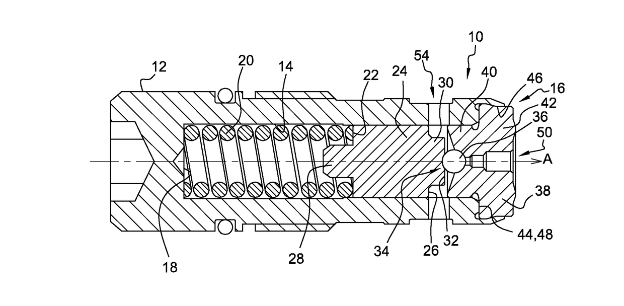
[0020]A pressure limiting valve 10 is described in reference to FIG. 1. The valve 10 is a mechanical valve although the invention is also applicable to electro-valves. A first usage of the valve 10 is to be arranged in a fuel injection equipment 8.

[0021]The valve 10 comprises a housing 12 provided with a central bore 14 extending along a longitudinal axis A from an opening 16, on the right of the housing 12 as per the orientation of the figure, to a blind end 18, on the left of the figure. Inside the bore 14, a spring 20 is compressed between the blind end 18 and the back face 22 of a piston 24 that is slidably arranged in the bore 14. The piston 24 is cylindrical and axially A extends from the back face 22 to a front face 26.

[0022]The back face 22 is centrally provided with a cylindrical protrusion 28 around which wind the last turns of the spring 20 and, the front face 26 is also axially A provided with a central cylindrical protrusion 30, the top face 32 of said front protrusion ...


PUM


Abstract

A pressure limiting valve communicates between a closed state, where a ball is biased against a valve seat along a contacting line and, an open state, where the ball is at a distance of the valve seat enabling fluid under pressure to exit via a relief orifice opening in the valve seat. The valve seat is shaped so that in the closed state of the valve, the contacting line between the ball and the valve seat is at a distance from the relief orifice opening.

Description

CROSS REFERENCE TO RELATED APPLICATIONS[0001]This application is a national stage application under 35 USC 371 of PCT Application No. PCT / EP2015 / 064072 having an international filing date of Jun. 23, 2015, which is designated in the United States and which claimed the benefit of GB Patent Application No. 1411856.6 filed on Jul. 3, 2014 the entire disclosures of each are hereby incorporated by reference in their entirety.TECHNICAL FIELD[0002]The present invention relates to a pressure limiting valve especially of the type used in fuel injection equipment's.BACKGROUND OF THE INVENTION[0003]A pressure limiting valve is a safety equipment arranged on a high pressure device for limiting to a predetermined threshold the pressure inside the device. In fuel injection equipment such a valve cooperates with a common rail that delivers high pressure fuel to a plurality of fuel injectors. The valve commutes between an open state enabling fuel exit from the rail and, a closed state where said ex...

Claims


Application Information

Patent Timeline
Patent Type & Authority Applications(United States)
IPC IPC(8): F16K17/04F02M61/18G05D16/10
CPCF16K17/0406F02M61/1886F02M61/188G05D16/103F02M63/005F02M63/0077F02M37/0029
Inventor ROUILLON, RAPHAELTRENADO, GUILLAUMESIMON, JEROME
Owner DELPHI TECH IP LTD
Learn More