
System for manufacturing laminted circuit boards

a technology of circuit board and manufacturing system, which is applied in the direction of auxilary welding device, mechanical control device, instrument, etc., can solve the problems of inability to enhance accuracy, increase the loss of quality control, and increase the loss of alignment accuracy, so as to reduce loss, accelerate repositioning, and rapidly form laminates

Active Publication Date: 2014-02-06
DUETTO INTEGRATED SYST
View PDF0 Cites 0 Cited by
  • Summary
  • Abstract
  • Description
  • Claims
  • Application Information

AI Technical Summary

Benefits of technology

This solution achieves improved layer-to-layer alignment accuracy (+ / −17 microns), reduced labor and operational cycles, and increased flexibility in panel sizes, minimizing waste and operational costs by eliminating tooling hole-related errors and the need for multiple tooling sets.

Problems solved by technology

Unfortunately, the Ceraso process, while more rapid, fails to enhance accuracy and commonly incurs higher quality control loses.
Unfortunately, these combined errors or “tolerance errors” build up throughout the course of lamination imaging and lamination tooling and ultimately have an exponential impact on alignment accuracy.
With the increasing reduction in dimensional circuit design these tolerance errors are unacceptable.
Imaging inner layers reveals internal alignment errors.
The downside to this method is that typically the same holes are used; and consequently, any distortion relative to these holes will have a negative affect as the inner layer is processed throughout the remainder of the lamination process.
This problem is greatly affected during lay-up and as the layer thickness is reduced.
Unfortunately, this edge imaging method still requires the use of holes for ultimate alignment of a completed lamination and hence still incurs alignment error.
Unfortunately, these tolerances exist regardless of the numbers of cameras used on a post-etch punch process.
Finally, as a further disadvantage in the conventional alignment arts, pin lamination is not flexible when changing panel sizes, shifting between panel sizes for custom lamination sets, etc.
When changing panel sizes, a customer needs to purchase different lamination and separator plates for each panel size to be processed, and this is extremely expensive.
Unfortunately, this process also has many of the same detrimental tolerance issues.
These detrimental tolerance issues include the need to line-up holes target locations prior to riveting, the need to punch or drill the holes, and ultimately after hole-creation the layers must be placed on pins prior to riveting to maintain alignment during the riveting process.
As noted in FIG. 2, the layer shift due to rivet distortion itself is a mechanical error that is very difficult to overcome, thus making the riveting generally a process for low layer count and low-density boards.
Unfortunately, pin bonding systems also possess some of the same tolerances.
The tolerance issues in pin bonding systems include that the line-up holes prior to bonding must be punched or drilled, and that the layers must be physically or mechanically placed on pins prior to bonding for the alignment.

Method used


Image

  • System for manufacturing laminted circuit boards
  • System for manufacturing laminted circuit boards
  • System for manufacturing laminted circuit boards

Examples


Embodiment Construction

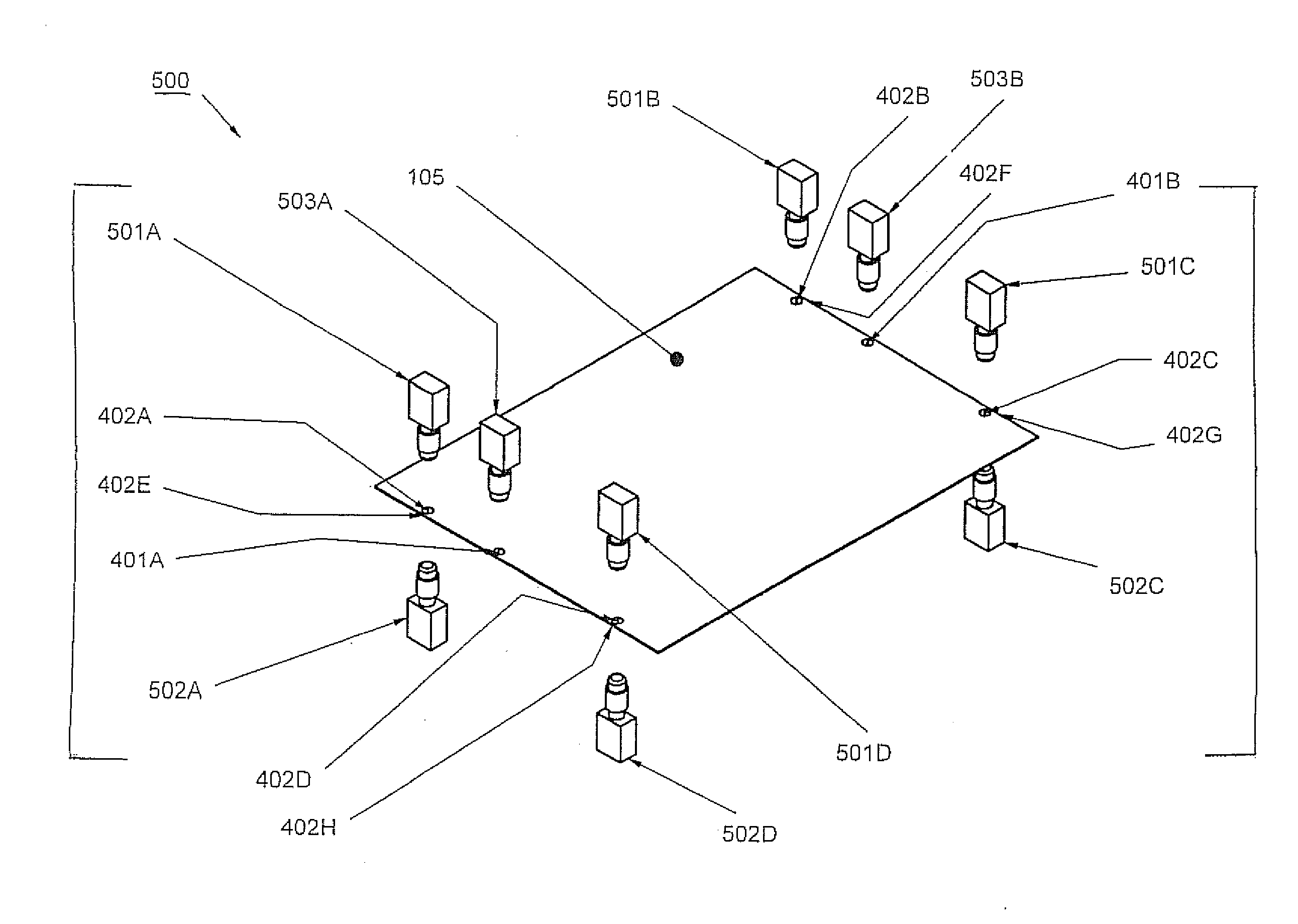
[0062]Reference will now be made in detail to several embodiments of the invention that are illustrated in the accompanying drawings. Wherever possible, same or similar reference numerals are used in the drawings and the description to refer to the same or like parts or steps. The drawings are in simplified form and are not to precise scale. For purposes of convenience and clarity only, directional teams, such as top, bottom, up, down, over, above, and below may be used with respect to the drawings. These and similar directional terms as should not be construed to limit the scope of the invention in any manner. The words “connect,”“couple,” and similar terms with their inflectional morphemes do not necessarily denote direct and immediate connections, but also include connections through mediate elements or devices.

A. Benefits of a Pin-less Registration System (PRS)—Initial Overview

[0063]In the presently proposed “Pin-Less Registration System,” the system combines the alignment accur...


PUM


Abstract

The present invention relates to a pin-less registration and inductive heating system involving the use of a pre-alignment station for imaging an initial position of a laminate element, an imaging and computer operation control system for determining a required correction factor between an alignment of the laminate element at the pre-alignment station and a preferred stack orientation for the laminate element, and an alignment and transfer system for securely gripping, transferring, and repositioning a laminate element from atop position to the preferred stack orientation employing a preferred four-axis orientation.

Description

CROSS REFERENCE TO RELATED APPLICATION[0001]This Application claims priority from PCT / US07 / 64435 filed Mar. 20, 2007 and U.S. Prov. App. Ser. No. 60 / 783,888 filed Mar. 20, 2006, the entire contents of which are herein incorporated by referenceFIGURE SELECTED FOR PUBLICATION[0002]FIG. 8BACKGROUND OF THE INVENTION[0003]1. Field of the Invention[0004]The present invention relates to an improved system and method for manufacturing laminated structures. More specifically, the present invention relates to an improved system and method for minimizing initial alignment error in printed circuit board (PCB) manufacturing.[0005]2. Description of the Related Art[0006]The related art involves a process for producing printed electronic circuits, including multilayer circuits by endothermic induction heading as discussed in PCT / IT2003 / 000403 by Ceraso, et al., (published as WO 2004 / 103042) [the Ceraso system] the entire contents of which are herein incorporated by reference.[0007]In the Ceraso pro...

Claims


Application Information

Patent Timeline
Patent Type & Authority Applications(United States)
IPC IPC(8): H05K3/00
CPCH05K3/00H05K1/0269H05K2201/09918H05K2203/065H05K2203/101H05K2203/107H05K2203/1476H05K2203/166H05K3/4638Y10T29/49213Y10T29/5317Y10T29/49126Y10T29/53087B23K37/04H05K2203/06H05K3/4691
Inventor FARACI, ANTHONYSORTINO, GARY N.
Owner DUETTO INTEGRATED SYST
Learn More