Hydraulic system

a technology of hydraulic system and valve body, which is applied in the direction of fluid coupling, servomotor, coupling, etc., can solve the problems of high losses in lines and valves, and achieve the effects of easy handling, increased or decreased maximum flow rate of the pump, and great sensitivity

Active Publication Date: 2013-04-30
DEERE & CO
View PDF8 Cites 1 Cited by
  • Summary
  • Abstract
  • Description
  • Claims
  • Application Information

AI Technical Summary

Benefits of technology

[0008]Accordingly, an object of this invention is to provide a hydraulic system which makes available a high flow rate at low engine rotational speeds, but that is limited to a certain maximum value at high engine rotational speeds.
[0009]This and other objects are achieved by the present invention, wherein a hydraulic system includes a flow control member for adjusting a flow of the pump. The flow control member is coupled to a piston, and the piston is engagable with a stop. The stop is controlled by an adjusting device which can be controlled by the control unit as a function of sensed engine speed. A predetermined maximum flow rate of the pump can be changed purposefully at the flow rate adjusting unit as a function of the engine speed so that with increasing engine speed the maximum flow rate conforms proportionally and a maximum flow rate is not exceeded.
[0011]When a predetermined engine speed is exceeded, the maximum flow rate of the pump can be reduced by controlling the adjusting devices at the stop of the adjusting pistons. The predetermined engine speed value that triggers the adjustment of the maximum flow rate can be provided as input depending upon the application preferable over an input module of an operator's display of an operating implement or any other appropriate input interface of the control unit. Depending on the maximum power output of the pump, a fixed engine speed value may already have been provided as input and stored in memory in the control unit.
[0013]Moreover for special applications provision is made to utilize the highest maximum volume flow of the pump. For this purpose, adjusting devices are provided as a function of which the control signal can be modified, and the stop of the adjusting piston can be changed by means of the adjusting devices, in such a way that the maximum flow rate of the pump can be increased regardless of the engine speed (or subsequently reduced again). In that way an operator can quasi “override” the control taken over from the control unit of the adjusting devices of the flow rate adjusting unit or at the stop of the adjusting piston and deactivate the control function of the control unit dependent upon the engine speed, by corresponding inputs at the adjusting devices, for example on an input module or at an input button with an adjusting wheel or a potentiometer, and modify the control signal by the direct input of an input signal, so that despite the generation of a control signal proportional to the engine speed, the signal that is provided as input to the adjusting devices is prioritized. Thereby it is possible to circumvent a control dependent upon the engine speed and to operate the hydraulic system with a large flow rate or to adjust any desired flow rate at each desired engine speed. There are particular applications in which the operator would desire to utilize the total pump capacity without regard to the power losses. One such application would be, for example, the operation of a front loader, in which the operator would like to attain the shortest possible cycle time and therewith more cyclic power. In such a case an pump with large flow rate would not help very much unless all lines and valves are increased to the same degree. Here it may then be useful to purposefully raise the maximum flow rate by a corresponding readjustment of the stop of the adjusting piston, in order to assure that the pump, or the flow rate adjusting unit of the pump or the swash plate can pivot fully, in order to deliver a greater flow rate.
[0015]The adjusting device for adjusting the position of the stop of the adjusting piston is preferably an electric motor which is controlled by the control unit. Moreover, an electromagnet could readjust the position of the stop. Preferably, the readjustment of the stop should occur directly, for example, by means of a stepper motor that is connected to a spindle drive, which converts a rotary movement of the motor into a linear movement of a spindle whose end can operate as a stop for the adjusting piston. The adjusting piston in turn either represents a stop for the flow rate control member (for example, for the swash plate) or it moves such a stop into a position through which the pivot angle of the flow rate adjusting unit can be readjusted or limited. As previously noted this readjustment can be performed electrically or electromagnetically, but also hydraulically, pneumatically or purely mechanically, where an electric or electromagnetic readjustment of the stop of the adjusting piston is preferred, since this is easier to handle than other means of readjustment. Now the readjustment of the stop can increase or decrease the maximum flow rate of the pump. The readjustment can also be performed, for example, by means of a proportional magnet that is effective in both directions. It is also conceivable that an adjustment in only one direction could be permitted. Since there always is a chance that the electronics on the operating vehicle fails, it is useful to provide measures that prevent a failure of the entire hydraulic system in case of a failure of the electronics. For this reason the application of a stepper motor is particularly appropriate for the repositioning of the stop of the adjusting piston. The stepper motor has the advantage that it has a certain degree of self locking and can be repositioned very precisely into a certain position (angle of rotation) which it does not leave unless it receives a new control signal or a very strong force is applied to it. Such a stepper motor can be connected, for example, to an adjusting spindle for the repositioning of the maximum stroke of an adjusting piston of a flow rate adjusting unit and can rotate this adjusting spindle very precisely and rapidly as a function of the control signal, so that the position of the adjusting piston and with it the maximum pivot angle of the swash plate of the flow rate control unit or the maximum flow rate of the pump can be readjusted with great sensitivity. Here the adjusting spindle or the end of the adjusting spindle that engages the adjusting piston represents the stop of the adjusting piston. If the electronics should fail, the stepper motor would simply remain stopped in its last position and thereby provide the assurance that at least a certain minimum operation of the hydraulic system is possible.
[0016]This hydraulic system optimally operates in all operating conditions of the vehicle that depend upon the drive and is used in particular for the reduction of power losses and for making available large flow rates at low engine speed. Moreover, existing smaller line cross sections and valves can be used despite an pump with a large flow rate. If necessary very large flow rates are possible despite smaller line cross sections and valves. The retention of the existing valves and lines is thereby possible, despite the use of a larger pump. Moreover, in case of failure of the electrical system assurance can be provided that the existing hydraulic system remains available despite electronic control of the flow rate controller.

Problems solved by technology

However, the pump has the possibility of conveying volume flows up to Vmax / min on the basis of its maximum conveying capacity, which would generate high losses in the lines and valves.

Method used


Image

  • Hydraulic system
  • Hydraulic system
  • Hydraulic system

Examples


Embodiment Construction

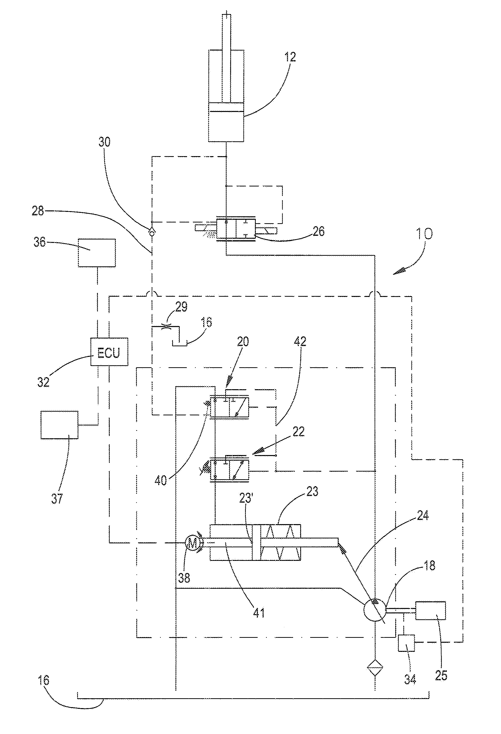
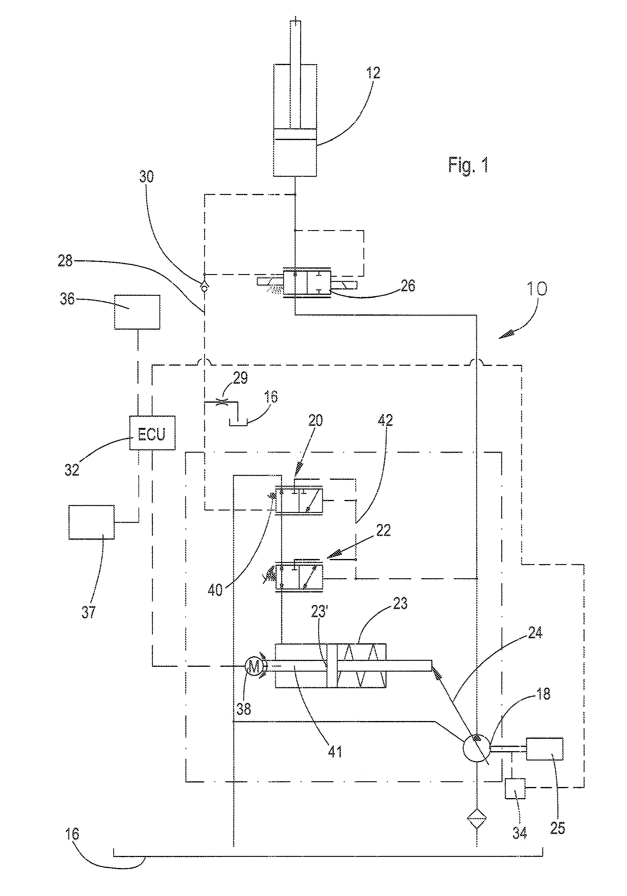
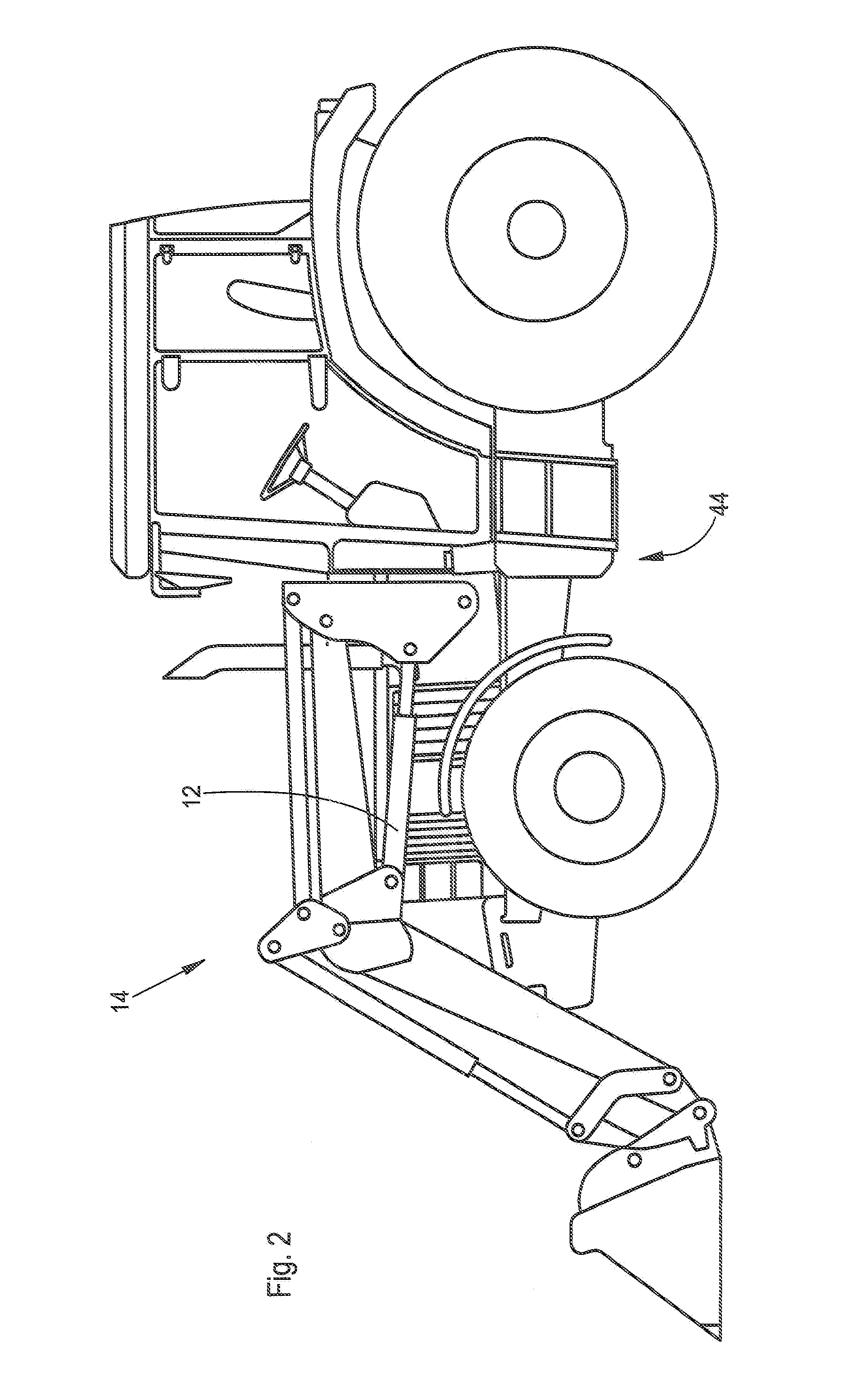
[0019]Referring to FIG. 1, the hydraulic system 10 supplies hydraulic fluid to a hydraulic consumer, such as a hydraulic cylinder 12, which lifts and lowers a front loader 14. The hydraulic system 10 includes a hydraulic reservoir 16, an adjustable or variable displacement hydraulic pump 18 with a flow rate controller 20 for the adjustment of a control pressure difference between the pump 18 and the cylinder 12, a pressure limiter 22 for the limitation of the operating pressure for the pump 18. The displacement of pump 18 is controlled by control or adjusting member 24, which is controlled by piston 23. Piston 23 engages a stop 23′ which limits the maximum displacement of the pump 18. The pump 18 is driven by an engine 25. A hydraulic control valve 26 controls communication between the cylinder 12 and the pump 18. A load pressure line 28 is connected between the cylinder 12 and the control valve 26, which is connected to the flow rate controller 20, where the load pressure line 28 i...


PUM


Abstract

A hydraulic system includes an engine driven variable displacement hydraulic pump which supplies fluid to a hydraulic consumer and an electronic control unit. A flow rate adjusting unit includes a stop that can be brought into engagement with an adjusting piston. In order conform the power output of the pump to the operating conditions of the vehicle, the stop of the flow rate adjusting unit includes adjusting devices that can be controlled by the control unit, so that the maximum flow rate of the pump can be varied by the electronic control unit. The electronic control unit generates a control signal for the adjusting device as a function of a sensed engine speed.

Description

FIELD OF THE INVENTION[0001]The present invention relates to a hydraulic system with an engine driven adjustable or variable displacement hydraulic pump which supplies hydraulic fluid to a hydraulic consumer under the control of an electronic control unit.BACKGROUND OF THE INVENTION[0002]Many types of agricultural or construction machines, such as tractors or telescopic loaders, have a hydraulic system which includes a hydraulic consumer, such as a hydraulic cylinder or hydraulic motor or other hydraulically driven components. Such hydraulic systems include hydraulic pumps that are connected with a drive shaft of the engine directly or over a rigid connecting gearbox that can be shifted into a fast or slow gear ratio. Thereby the maximum volume flow of the hydraulic pump varies with the rotational speed of the engine. The more rapidly the engine rotates, the larger is the pump flow rate. With adjustable or variable displacement hydraulic pumps, the maximum flow rate may be made to c...

Claims


Application Information

Patent Timeline
Patent Type & Authority Patents(United States)
IPC IPC(8): F16D31/02F01B3/00F15B15/24
CPCF15B11/055F15B2211/20553F15B2211/40561F15B2211/633F15B2211/7052
Inventor BAUER, WOLFGANG
Owner DEERE & CO
Why Eureka
Try Eureka