Display device and input device

a technology which is applied in the field of display device and input device, can solve the problems of detection error, long increased power consumption, etc., and achieve the effect of preventing or suppressing the occurrence of detection error, shortening the time taken for detection process, and reducing time taken

Active Publication Date: 2017-06-08
JAPAN DISPLAY INC
View PDF1 Cites 12 Cited by
  • Summary
  • Abstract
  • Description
  • Claims
  • Application Information

AI Technical Summary

Benefits of technology

[0009]The present invention is made in order to solve the problem of a conventional technique as described above. The purpose of the present invention is to provide an input device and a display device capable of preventing or suppressing occurrence of a detection error while reducing a time taken for a finger proximity detection process and reducing power consumption in the finger proximity detection process performed as a standby mode before a finger coordinate detection process as a detection mode.

Problems solved by technology

However, in the finger proximity detection process, in a case in which electrostatic capacitance of each of the plurality of detection electrodes is detected by switching the plurality of detection electrodes in groups and connecting the plurality of detection electrodes to the detection circuit in the same manner as in the finger coordinate detection process, there is a problem that a longer time is taken for the detection process or power consumption increases.
In contrast, in a case in which the plurality of detection electrodes are partly selected in groups in order to shorten the time taken for the detection process or a waiting time for repeating the detection process is prolonged, a detection error may occur.

Method used


Image

  • Display device and input device
  • Display device and input device
  • Display device and input device

Examples


first embodiment

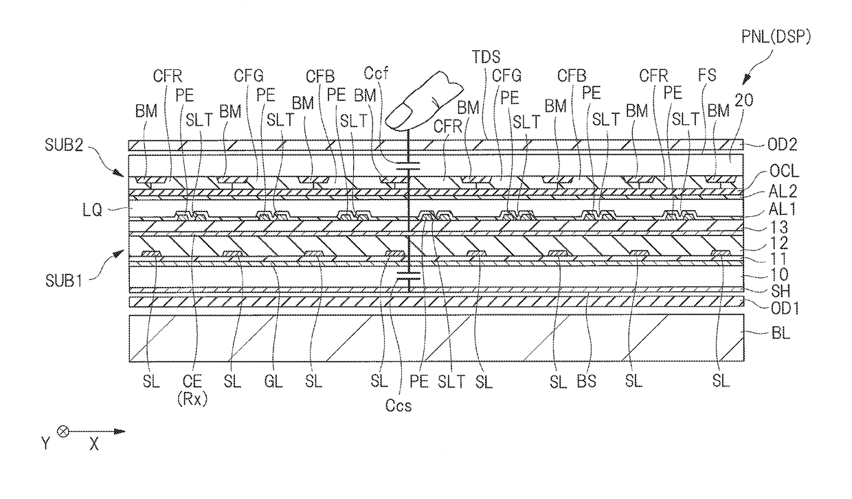
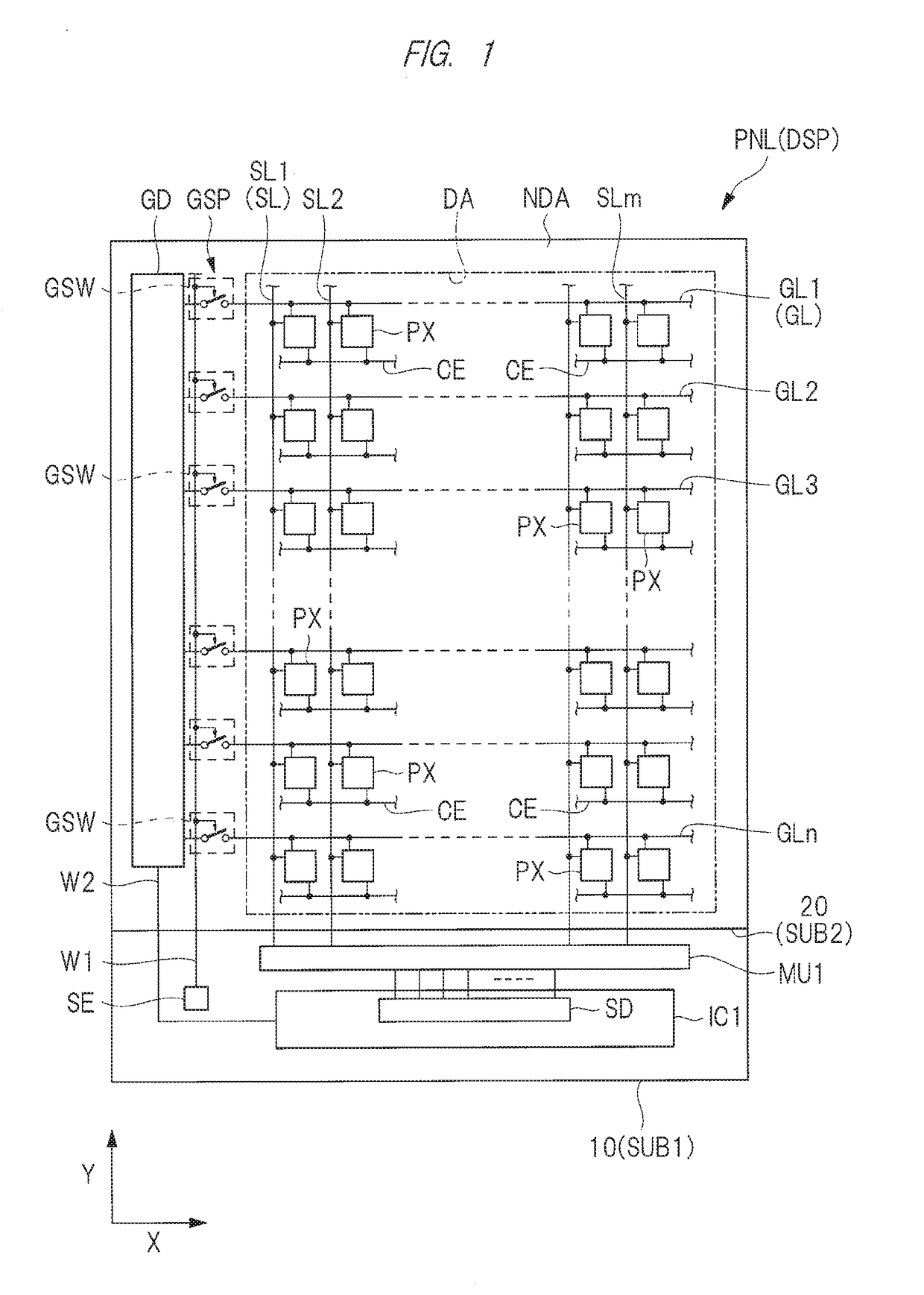
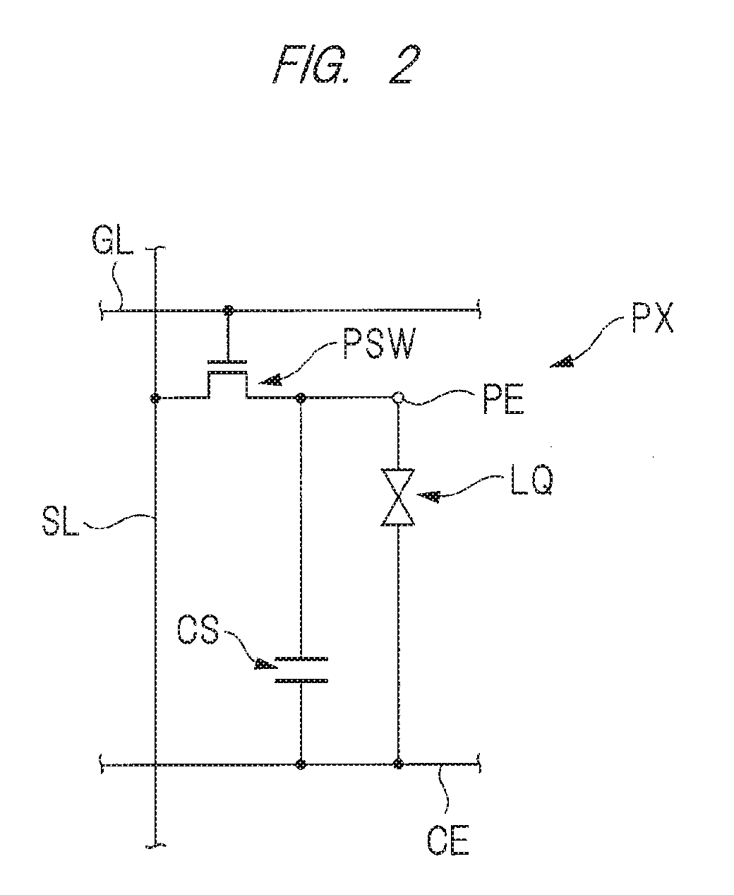
[0046]First, as a first embodiment, a description is given of an example in which a touch panel as an input device is applied to an in-cell display device with a touch detection function where a detection electrode of the input device is provided in a display panel of the display device and functions as a common electrode of the display device. Here, the display device according to the present first embodiment is a liquid crystal display device. Note that, in the present specification, the input device is an input device configured to at least detect electrostatic capacitance which changes depending on capacitance of an object in proximity to or in contact with an electrode. Here, as a method of detecting electrostatic capacitance, a self-capacitance method of detecting electrostatic capacitance of a single electrode may be used. In addition, the in-cell display device with a touch detection function means a display device with a touch detection function having a feature that a driv...

first modification example of first embodiment

[0201]Next, a first modification example of the first embodiment will be described. FIG. 24 is a diagram illustrating a touch detection circuit in the first modification example of the display device according to the first embodiment. Note that FIG. 24 illustrates a case where each of a plurality of shield electrodes SH is selected in step S11 by hatching the plurality of shield electrodes SH.

[0202]The display device according to the present first modification example is different from the display device according to the first embodiment in that a shield electrode is divided into the plurality of shield electrodes SH, and the display device according to the present first modification example is similar to the display device according to the first embodiment for the rest. That is, the display device according to the first embodiment includes one shield electrode SH; however, the display device according to the first modification example includes the plurality of shield electrodes SH....

second modification example of first embodiment

[0207]Next, a second modification example of the first embodiment will be described. FIG. 25 is a cross-sectional view illustrating an example of the second modification example of the display device according to the first embodiment. FIG. 26 is a diagram illustrating a touch detection circuit in another example of the second modification example of the display device according to the first embodiment.

[0208]The display device according to the present second modification example is different from the display device according to the first modification example of the first embodiment in that a plurality of shield electrodes SH (see FIG. 24) and a connection circuit CNC2 (see FIG. 24) are not provided and a change in electrostatic capacitance of each of a plurality of scan lines GL or a plurality of signal lines SL instead of a plurality of shield electrodes SH is detected in step S11. As for the rest, the display device according to the present second modification example is similar to...


PUM

PropertyMeasurementUnit
frequencyaaaaaaaaaa
electrostatic capacitanceaaaaaaaaaa
electrostatic capacitance detectionaaaaaaaaaa

Abstract

A display device includes: a display panel having a front surface and a back surface and displaying an image on the front surface; a plurality of detection electrodes overlapping the display panel when seen in a plan view; and a shield electrode overlapping the display panel when seen in a plan view. The shield electrode is arranged on a side opposite to a side of the front surface with respect to the plurality of detection electrodes. Based on electrostatic capacitance of the shield electrode, proximity or contact of an object to the front surface is detected, and based on electrostatic capacitance of each of the plurality of detection electrodes, a position of the object is detected.

Description

CROSS-REFERENCE TO RELATED APPLICATION[0001]The present application claims priority from Japanese Patent Application No. 2015-237258 filed on Dec. 4, 2015, the content of which is hereby incorporated by reference into this application.TECHNICAL FIELD OF THE INVENTION[0002]The present invention relates to a display device and an input device.BACKGROUND OF THE INVENTION[0003]In recent years, there is a technique where an input device called a touch panel or a touch sensor is attached to a display surface of a display device and an input position is detected and output when an input operation is performed by bringing an input tool such as a finger or a touch pen into contact with the touch panel.[0004]An example of the detection methods for detecting a contact position where a finger or the like contacts a touch panel serving as such an input device is an electrostatic capacitance detection method. In a touch panel using the electrostatic capacitance detection method, a plurality of ca...

Claims


Application Information

Patent Timeline
Patent Type & Authority Applications(United States)
IPC IPC(8): G06F3/041G02F1/1333G02F1/1343G06F3/044
CPCG06F3/0416G06F3/0412G06F3/044G02F1/13439G02F1/134336G06F2203/04108G02F1/13338G06F2203/04107G06F3/04166G06F3/0443
Inventor SUZUKI, TAKAFUMI
Owner JAPAN DISPLAY INC
Why Eureka
Try Eureka