
Rocker arm and method of manufacturing the same

a technology of rocker arm and screw, which is applied in the direction of mechanical control devices, instruments, process and machine control, etc., can solve the problems of insufficient countermeasures to the lubricating state of the sliding contact face of the valve stem becomes more severe, and the occurrence of abnormal abrasion and pitching is not easy to prevent or suppress. effectively prevent the occurrence of abnormal abrasion and pitching, and effectively preven

Active Publication Date: 2005-08-04
JTEKT CORP
View PDF9 Cites 2 Cited by
  • Summary
  • Abstract
  • Description
  • Claims
  • Application Information

AI Technical Summary

Benefits of technology

The present invention provides a rocker arm that prevents abnormal abrasion and pitching on the sliding contact face of the valve stem. This is achieved by improving the hardness and retained austenite content of the rocker arm. The valve stem receiver is formed by integrating a connecting wall between the opposed side walls of the rocker arm. Dimples are formed on the sliding contact face of the valve stem receiver to hold lubricant and prevent abnormal abrasion and pitching. The method of manufacturing the rocker arm involves carburizing, quenching, and tempering the surface layer portion of the valve stem with a Vickers hardness of Hv 650 to 800 and a quantity of retained austenite of γR25 to 35 vol%. The invention also provides a low carbon steel with a Vickers hardness of Hv 650 to 800 and a quantity of retained austenite of γR25 to 35 vol%.

Problems solved by technology

A lubricating state on the sliding contact face of the valve stem receiver of the rocker arm made of sheet metal, on which the valve stem slides and contacts, is not so good, so that abnormal abrasion and pitching tend to occur on the sliding contact face.
However, when the viscosity of engine oil used as lubricant is decreased, the lubricating state of the sliding contact face of the valve stem becomes more severe, and the above countermeasure for preventing the occurrence of abnormal abrasion and pitching is not sufficient.

Method used


Image

  • Rocker arm and method of manufacturing the same
  • Rocker arm and method of manufacturing the same
  • Rocker arm and method of manufacturing the same

Examples


Embodiment Construction

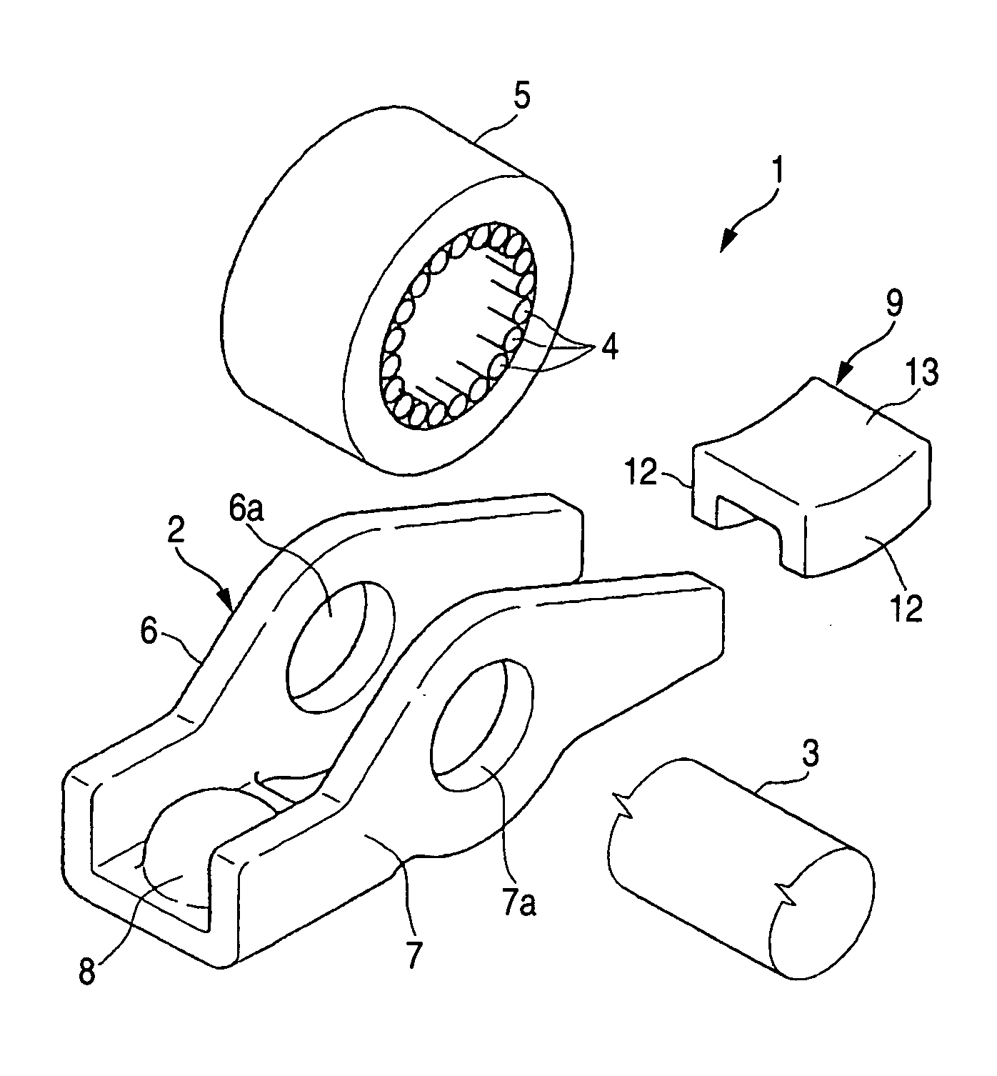
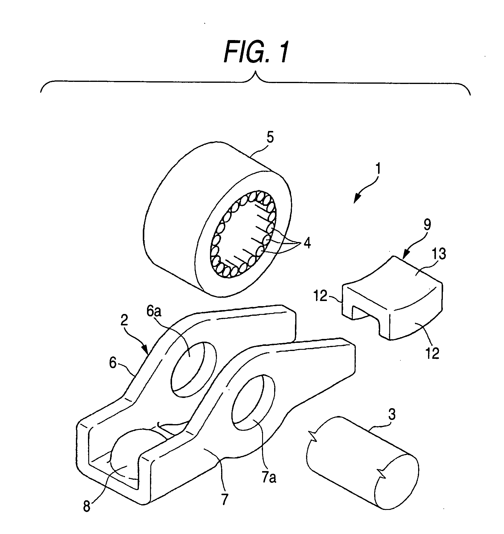
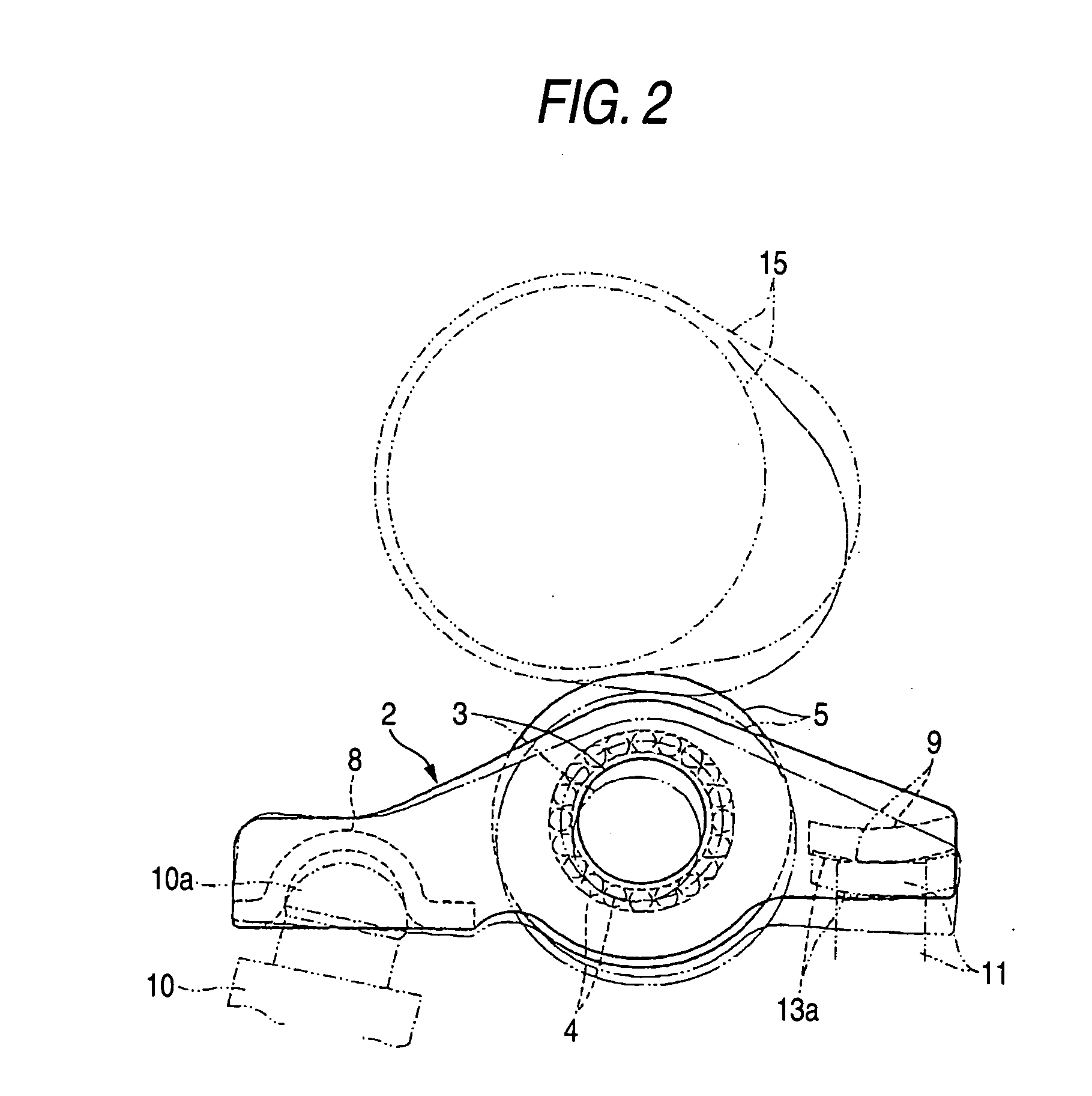
[0021] Referring to the accompanying drawings, the embodiment according to the present invention will be described below. FIG. 1 is an exploded perspective view showing an overall arrangement of a rocker arm, FIG. 2 is a sectional view of the rocker arm viewed at the center in the width direction, FIG. 3 is an enlarged sectional view showing a state of contact of the connecting wall of the rocker arm with a valve stem, and FIG. 4 is a graph showing a relation between the repetition number and the quantity of abrasion.

[0022] Referring to these views, reference numeral 1 defines a rocker arm made of sheet metal. The rocker arm is provided with a body 2. The body 2 includes a pair of opposed side walls 6, 7. The opposed side walls 6, 7 respectively include the spindle holes 6a, 7a for supporting the spindle 3 in the respective central region in the longitudinal direction. The spindle 3 is nonrotatably assembled to the opposed side walls 6, 7 by press fitting end portions of the spindl...


PUM

PropertyMeasurementUnit
Vickers hardnessaaaaaaaaaa
surface pressureaaaaaaaaaa
viscosityaaaaaaaaaa

Abstract

A rocker arm 1 made of sheet metal is formed so that Vickers hardness Hv of the surface layer portion 9a of the valve stem receiver 9 is set at Hv 650 to 800 and a quantity of the retained austenite γR is set at 25 to 35 vol %.

Description

BACKGROUND OF THE INVENTION [0001] The present invention relates to a rocker arm made of sheet metal used for a valve gear of an automobile engine, and a method of manufacturing the rocker arm. [0002] A rocker arm made of sheet metal provided in a valve gear of an automobile engine is formed in such a manner that a roller is arranged between a pair of opposed side walls provided in a body made of sheet metal and this roller is pivotally supported by a spindle via needle rollers. Connecting walls are formed so as to respectively connect the opposed side walls to each other and are arranged in the longitudinal direction. One of the connecting walls is used as a lash adjuster receiver and the other connecting wall is used as a valve stem receiver. [0003] In this rocker arm made of sheet metal, when a cam is contacted with the roller and rolled on it and the body is oscillated round the lash adjuster which functions as a fulcrum, and the valve stem is moved upward and downward by the va...

Claims


Application Information

Patent Timeline
Patent Type & Authority Applications(United States)
IPC IPC(8): F01L1/047F01L1/18F01L3/02
CPCC21D2211/001F01L1/185F01L3/04F01L2101/00Y10T74/20882F01L2105/02Y10S148/003Y10T74/2107Y10T29/49295F01L2103/00F01L2301/00F01L2303/00F01L2305/02
Inventor MOTOHASHI, NOBUTSUNA
Owner JTEKT CORP
Learn More