Ignition device

a technology of ignition device and ignition chamber, which is applied in the direction of engine ignition, ignition circuit layout, machines/engines, etc., can solve the problems of affecting the performance affecting the ignition quality of the ignition device, so as to prevent and/or suppress the occurrence of serious damage

Active Publication Date: 2018-05-17
MITSUBISHI ELECTRIC CORP
View PDF17 Cites 1 Cited by
  • Summary
  • Abstract
  • Description
  • Claims
  • Application Information

AI Technical Summary

Benefits of technology

[0010]The present invention has been made to solve the aforementioned problem, and an object of the present invention is to prevent and / or suppress the occurrence of serious damage due to an electric shock in an ignition device having high voltage wiring which may cause an electric shock.
[0012]According to the ignition device according to the present invention, the ignition device includes: the ignition plug that generates the plasma discharge; the DC / AC conversion device that outputs the AC power in which the DC power is converted into the AC power toward the ignition plug; the DC power supply device which is arranged in the different package from that of the DC / AC conversion device, generates the DC power that is for being converted into the AC power by the DC / AC conversion device, and outputs the DC power to be supplied to the DC / AC conversion device via the wiring; and the power circuit breaker that conducts and / or interrupts the output of the DC power supply device. The power circuit breaker interrupts the output of the DC power supply device at least once between the ignition operation and the ignition operation, whereby a continuous electric shock can be prevented and the occurrence of serious damage can be prevented and / or suppressed.

Problems solved by technology

However, combusted gas, which is exhaust air, is incombustible and has a larger thermal capacity than that of air; and accordingly, if a large amount of combusted gas is sucked again by the EGR, a problem exists in that ignition quality and combustion quality deteriorate.
However, when the voltage of the energy supply section connected to the driving circuit by wiring is raised, an electric shock and / or a leak may be caused by coating deterioration of the wiring, a fitting defect of a connector, a disconnection, and the like.

Method used


Image

  • Ignition device
  • Ignition device
  • Ignition device

Examples


embodiment 1

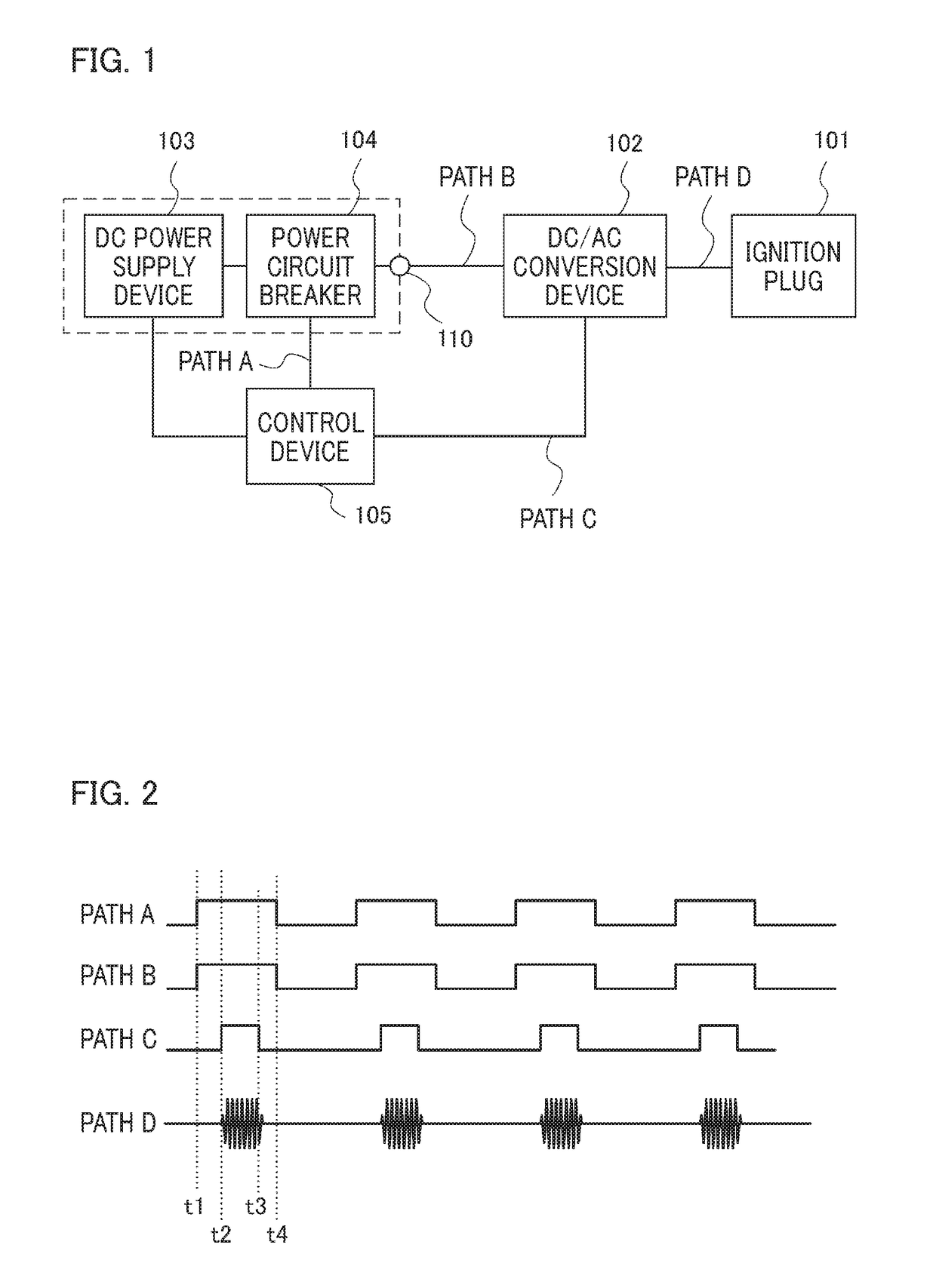
[0022]FIG. 1 is a configuration diagram of an ignition device in an internal combustion engine that performs intermittent combustion according to Embodiment 1 of the present invention.

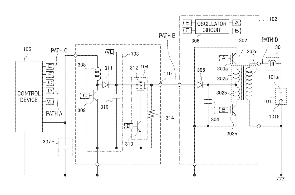
[0023]In FIG. 1, the ignition device according to Embodiment 1 of the present invention includes: an ignition plug 101; a DC / AC conversion device 102 which supplies AC power that is for generating a plasma discharge by the ignition plug 101; a DC power supply device 103 that supplies DC power to the DC / AC conversion device 102; a power circuit breaker 104 that performs switching between interruption and conduction of output power (DC power) of the DC power supply device 103; and a control device 105 that controls the operation of the power circuit breaker 104.

[0024]A high frequency AC and high voltage power come and go between the DC / AC conversion device 102 and the ignition plug 101.

[0025]Accordingly, in order to suppress radiation noise and / or in order to improve the transmission efficiency of the po...

embodiment 2

[0064]Most parts of Embodiment 2 have the same configuration as that of the ignition device of Embodiment 1; however, in addition to the configuration, Embodiment 2 provides a safer ignition device that can prevent the destruction of the device and / or a leak by configuring so as to determine whether or not a power circuit breaker 104 is set to be a conduction state after confirming a connection state of a path B.

[0065]The operation of the power circuit breaker 104 will be described by using a configuration diagram of FIG. 5 and a timing chart of FIG. 6. For example, as shown in FIG. 5, a 5 volt power supply 401 is arranged in a DC / AC conversion device 102. An output of 5 v is connected to the path B via a diode 402. The 5 volt power supply 401 and the diode 402 constitute a conduction confirmation device which confirms that wiring (path) through which the output of a DC power supply device 103 is connected to the DC / AC conversion device 102 is connected, and outputs a result of cond...


PUM


Abstract

In an ignition device having high voltage wiring, the ignition device which prevents and / or suppresses the occurrence of serious damage due to an electric shock is provided. In the ignition device which includes: an ignition plug that generates a plasma discharge; a DC / AC conversion device that outputs AC power toward the ignition plug; a DC power supply device which is arranged in a different package from that of the DC / AC conversion device and outputs DC power to the DC / AC conversion device via wiring; and a power circuit breaker that conducts and / or interrupts the output of said DC power supply device, the power circuit breaker interrupts the output of the DC power supply device at least once between ignition operation and ignition operation.

Description

BACKGROUND OF THE INVENTION1. Field of the Invention[0001]The present invention relates to an ignition device that mainly uses a plasma discharge by alternative current (AC) power.2. Description of the Related Art[0002]In recent years, the problem of environmental conservation and fossil fuel depletion has been raised and it becomes an urgent need to deal with these also in the automotive industry. As an example dealing with this, there is a method of dramatically improving the amount of fuel consumption by reducing a pumping loss by the use of exhaust gas recirculation (EGR).[0003]However, combusted gas, which is exhaust air, is incombustible and has a larger thermal capacity than that of air; and accordingly, if a large amount of combusted gas is sucked again by the EGR, a problem exists in that ignition quality and combustion quality deteriorate.[0004]As one of solutions of this problem, there has been proposed an ignition device shown in, for example, Patent Document 1, in which...

Claims


Application Information

Patent Timeline
Patent Type & Authority Applications(United States)
IPC IPC(8): F02P7/06F02P1/08
CPCF02P1/08F02P7/06F02P3/01
Inventor TANAYA, KIMIHIKO
Owner MITSUBISHI ELECTRIC CORP
Why Eureka
Try Eureka