
Visual modeling method to construct system views based on a system meta view

Inactive Publication Date: 2017-06-08
CHENGDU PUZHONG SOFTWARE CO LTD
View PDF1 Cites 3 Cited by
  • Summary
  • Abstract
  • Description
  • Claims
  • Application Information

AI Technical Summary

Benefits of technology

The present invention provides a system view with easy-to-use elements and methods. It is simple to construct and can be used by people with no experience in modeling or programming. This saves time and reduces communication with professionals, resulting in a more fitting system view and fewer understanding errors. Overall, the invention simplifies the process of creating a system view with executable code.

Problems solved by technology

However, most of the system views are always limited to a certain type of descriptions of the system models rather than providing a universal description for general system view.
For system modeling, the UML has the following drawbacks: Firstly, UML cannot provide modeling methods: UML clearly states that it does not provide modeling methods and is only a descriptive language for modeling methods; UML is oriented towards programmers, targeting the development of modeling products in the software development process.
Secondly, the lack of executability thereof is a fatal drawback: the UML lacks a rigorous theoretical support for modeling, which has been criticized by insiders; the deficiency of completeness and consistency results in a system view constructed by the UML being lack of executability, i.e., the view described by using UML cannot be directly converted into an executable software.
This drawback makes the UML only be a supplementary expression tool for a system view rather than a true system meta view.
Thirdly, it is difficult to understand and use: the UML creates a lot of concepts, relations and diagrams.
Relationships among these concepts, relations, and diagrams are loose and numerous.
However, the UML's complication and disorder are not only hard for programmers to grasp, but also even more difficult for industry experts to understand, far from satisfying the needs of modeling.
There are basic drawbacks in this visual modeling method based on assembling of prefabricated components: firstly, the system model must be assembled based on the prefabricated components so that the construction of the system model is seriously subject to the prefabricated components; interfaces of the prefabricated components are invariable so that such a visual modeling method is usually applied in specific sector-modeling based on a library of the components rather than suitable for a universal system modeling because it does not support to integrate the components with arbitrary interfaces; secondly, rules for assembling and operating the components are very simple as well and are basically working synergies among the components decided by transfer relationships of data complexity for the transfer of the data makes readability of the view dramatically deteriorated as the number of the components increases, so that this method is actually applied only to describe relatively simple algorithms rather that largely complex systems though it is declared to be used in the system modeling.

Method used


Image

  • Visual modeling method to construct system views based on a system meta view
  • Visual modeling method to construct system views based on a system meta view
  • Visual modeling method to construct system views based on a system meta view

Examples


Embodiment Construction

[0113]Generally, a computer comprises a central processor, a memory, an Input and Output (I / O) interface, and a bus; and furthermore, the computer is connected with an input and output device and a storage medium. The central processor takes charge of functions of computing and controlling the computer. The central processor may only include one central processing unit, or may include a plurality of central processing units distributed at one or more positions.

[0114]The memory medium may be formed by any known computer readable storage medium. For example, a buffer memory may temporarily store some program codes so as to reduce time for extracting codes from a large-capacity memory when the program is run. In the meantime, the memory may reside at a certain physical position, and may be stored in one or more types of data, or may be distributed in different physical systems in different forms. Moreover, the memory may also be distributed in a Local Area Network (LAN) or a Wide Area ...


PUM


Abstract

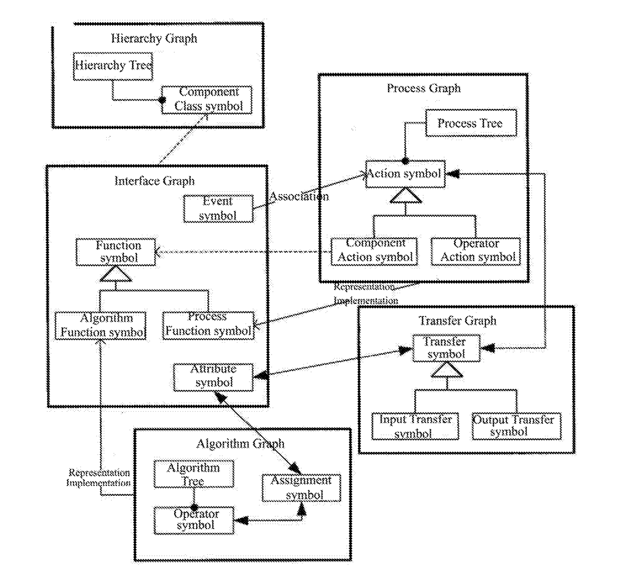
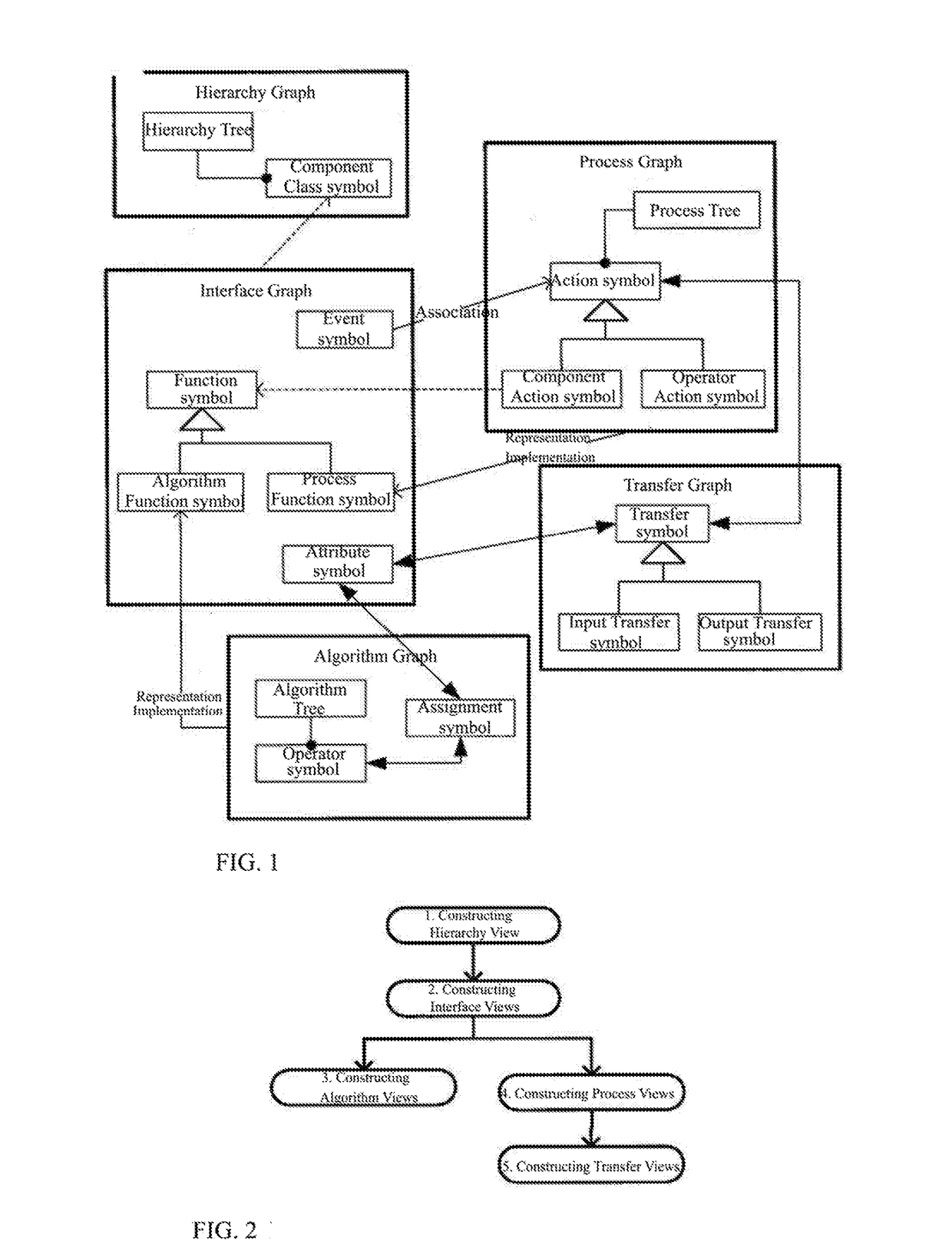
A system element view-based visual modeling method for constructing system view. After determining basic constituents of the system element view, the present invention constructs system views through a hierarchy view, interface views, algorithm views, process views, and transfer views as step features and thereby provides a specification for visual system modeling in modeling in various fields; such specification has advantages including generality and convenience; system views constructed through the present invention are executable, have clear structures, adjustable hierarchies, and controllable granularities; this modeling method supports both top-down analysis and bottom-up integration for modeling in various systems including software systems and information systems. The modeling method is simple and completely visual, thereby even those not skilled in any modeling language nor computer programming language can easily and independently construct the system view, eliminating the tedious and unnecessary communication with and dependence on professional modelers and application developers, greatly reducing modeling time.

Description

TECHNICAL FIELD[0001]The present invention relates to the technical field of software engineering, and more specifically, it is a visual modeling method based on system meta view for constructing system views and a computer program product thereof.TECHNICAL BACKGROUND[0002]A system is a joint name for objects and events in the real or imaginary world, and a system model refers to a structured description of knowledge about the objects, especially complex objects. System modeling is an action or a process in which a system model is constructed based on laws and features of the objects. Long before the emergence of software, system modeling already exists widely in various practical social activities such as scientific research, engineering, military, and industries. With developing of the system modeling activity, there are a variety of representations of the system model, such as by a language, a text, a formula, a graph, and so on. Compared with other representations of the system ...

Claims


Application Information

Patent Timeline
IPC IPC(8): G06F9/44
CPCG06F8/35G06F8/10G06F8/34
Inventor FU, CHANGMING
Owner CHENGDU PUZHONG SOFTWARE CO LTD
Learn More