

Combination dimmable driver
a technology of dimmable drivers and dimmable components, which is applied in lighting devices, electrical appliances, lighting designers, etc., can solve the problems of not being compatible, not working properly, and existing step dimming drivers, so as to maximize flexibility, extend compatibility, and ensure the effect of quality
- Summary
- Abstract
- Description
- Claims
- Application Information
AI Technical Summary
Benefits of technology
Problems solved by technology
Method used
Image

Examples
Embodiment Construction
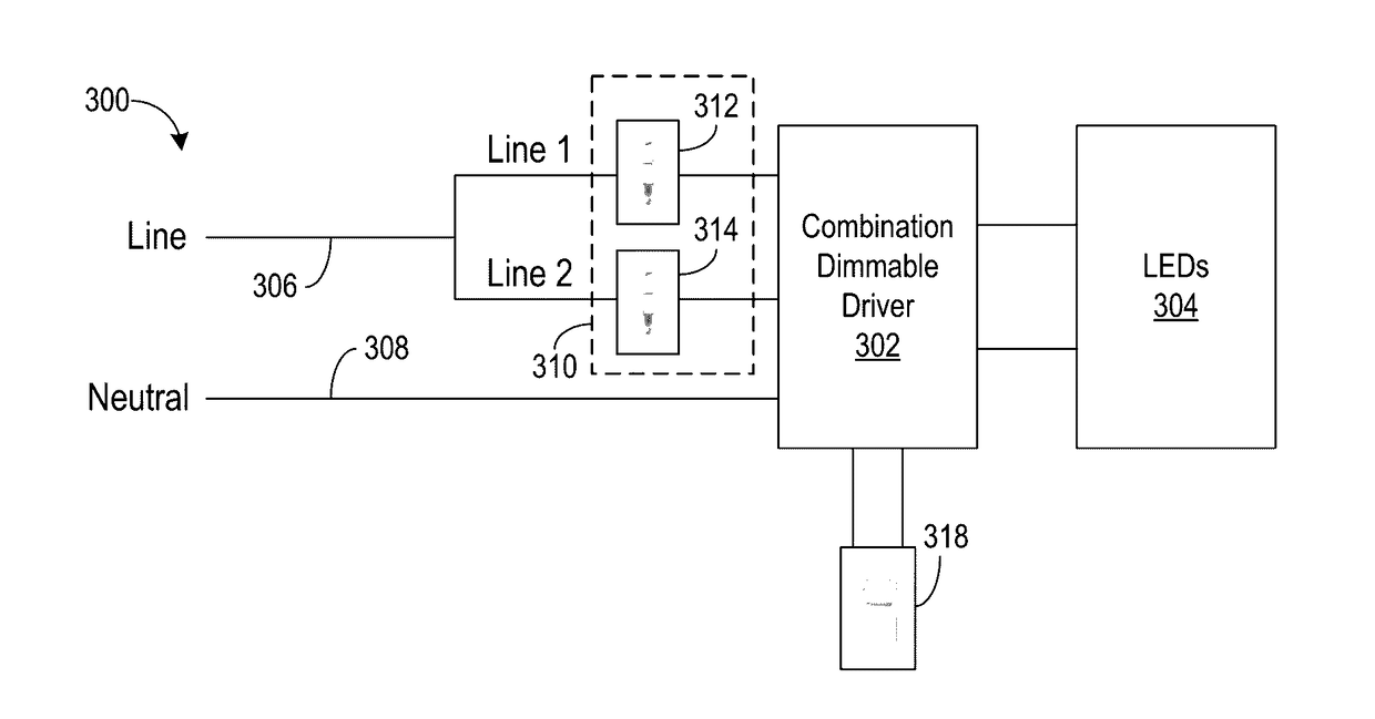
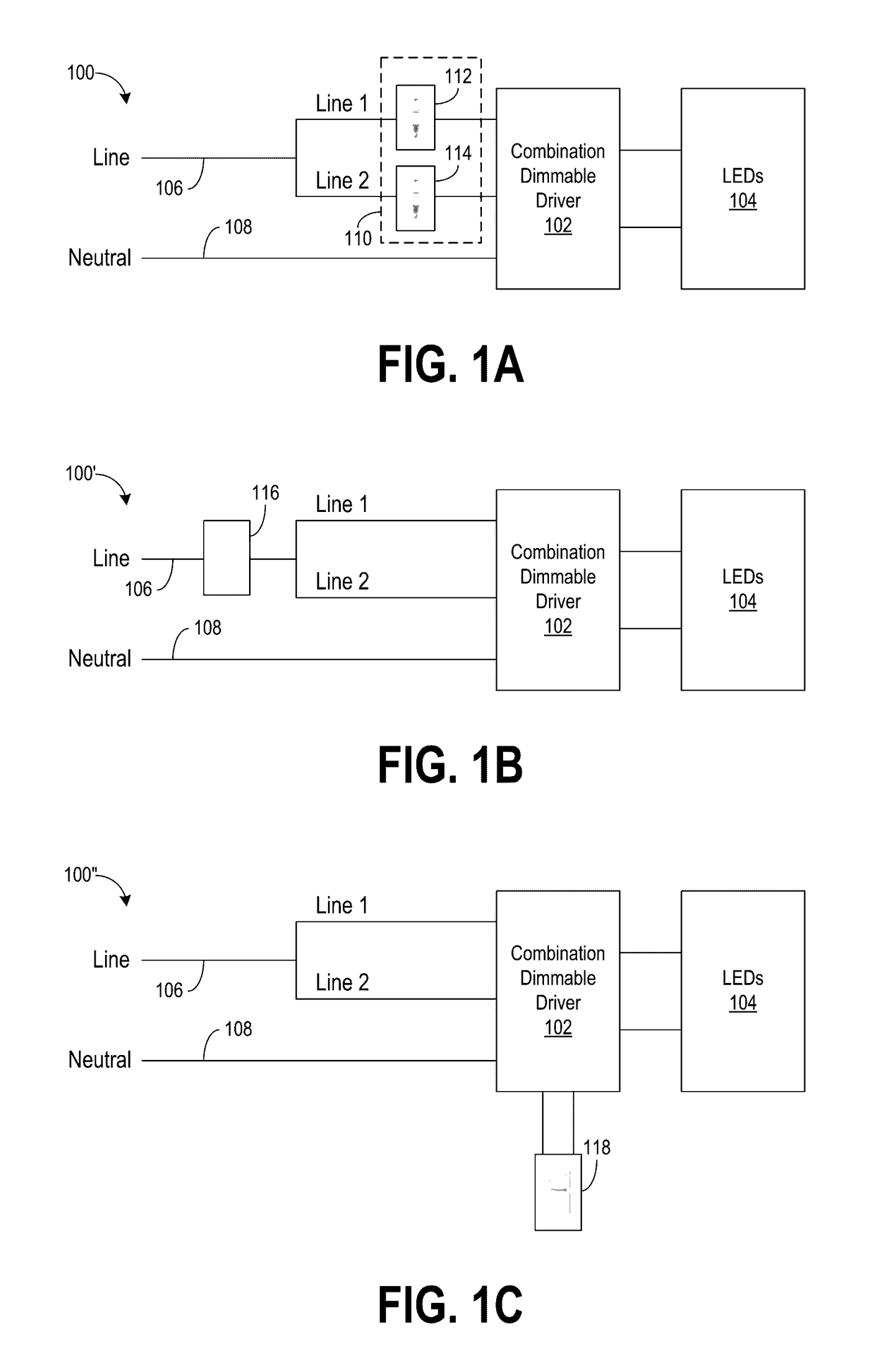
[0007]The disclosed embodiments are directed to a method and system for dimming LEDs in a light fixture using a dimmable driver that can operate with multiple dimming protocols. The method and system is able to achieve expanded compatibility by combining several of the most widely used dimming protocols into one dimmable driver. This combining allows the dimmable driver to be disconnected from one type of dimmer and subsequently connected to another type of dimmer without having to replace or otherwise adjust the driver for each dimmer. Such a combination dimmable driver may be then installed in any LED or other solid-state lighting fixture to allow the lighting fixture to accommodate multiple types of dimmers. The resulting lighting fixture may thereafter be used in any number of lighting applications with high confidence that there will be no compatibility issues with the dimmer. This maximizes flexibility for lighting specifiers, contractors, and distributors while minimizing pot...
PUM
 Abstract
Description
Claims
Application Information