
Control device for vehicle suspension

a control device and vehicle technology, applied in the direction of resilient suspensions, springs/dampers, vehicle components, etc., can solve the problems of deteriorating the ride comfort of the vehicle, strong pitch behavior likely to occur, significant sprung mass behavior on the rear wheel side, etc., to achieve stable vehicle behavior and comfortable ride

Inactive Publication Date: 2017-06-22
TOYOTA JIDOSHA KK
View PDF0 Cites 2 Cited by
  • Summary
  • Abstract
  • Description
  • Claims
  • Application Information

AI Technical Summary

Benefits of technology

The present invention proposes a control device for a vehicle suspension system that is effective in suppressing a pitch behavior when the front wheel crosses a bump, while maintaining a comfortable ride when the rear wheel crosses the bump. This is achieved by setting the damping coefficient of the shock absorber of the rear wheel to the hard-side value when a sprung mass behavior is occurring on the front wheel, and the damping coefficient of the rear wheel to the soft-side value when the rear wheel reaches the rising point on the road surface. The control device can accurately calculate the required time for the rear wheel to reach the rising point, and can perform individual control for each pair of left and right wheel to achieve both stable vehicle behavior and the comfortable ride at a high level.

Problems solved by technology

In this regard, the suspension device as set forth in Patent Literature 1 has a problem in that a strong pitch behavior is likely to occur when the front wheel crosses the bump, although the suspension device is effective for suppressing push-up when the rear wheel goes over the bump that front wheel has previously overcome.
When the front wheel goes over the rising point on the road surface, the resultant oscillation is transmitted to the rear wheel, which may cause a significant sprung mass behavior on the rear wheel side.
If the damping coefficient regarding the rear wheel is kept at the hard-side value even when the rear wheel crosses the rising point, a strong push-up force is likely to be transmitted to a passenger in the vehicle, which can cause deterioration of the ride comfort of the vehicle.

Method used


Image

  • Control device for vehicle suspension
  • Control device for vehicle suspension
  • Control device for vehicle suspension

Examples


first embodiment

Characteristics Of First Embodiment

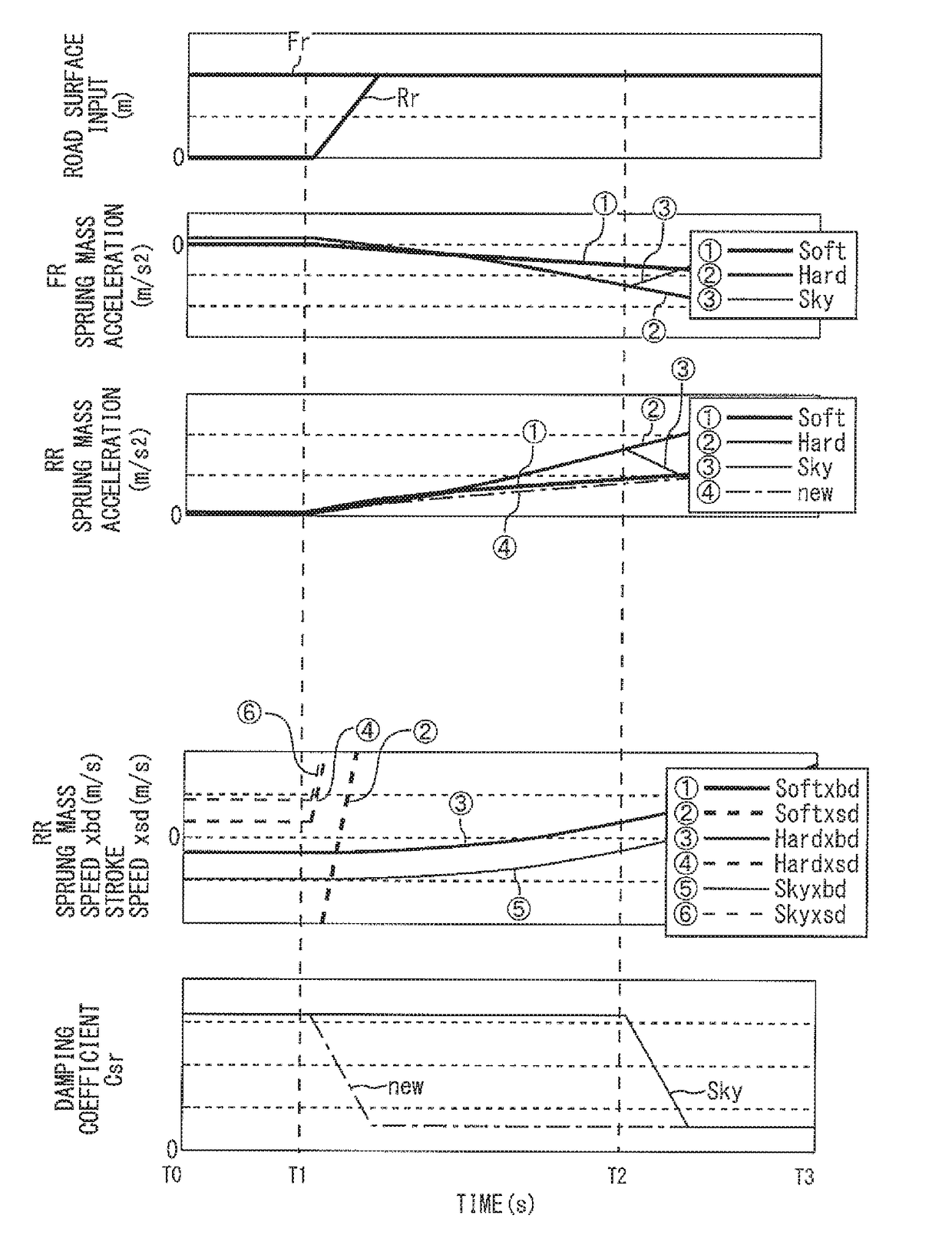
[0059]However, according to the control in the comparative example described above, when the rear wheel 34 goes over the rising point 54 on the road surface at the time t0, the high sprung mass acceleration 60 inevitably occurs for a short time. On the other hand, according to the present embodiment, it is possible to prevent such the high sprung mass acceleration from occurring, by switching the damping coefficient Csr for the rear wheel 34 to the soft-side value at the same time as the rear wheel 34 reaches the rising point 54.

[0060]FIG. 6 is a timing chart for explaining a vehicle behavior in a case where the control according to the present embodiment for achieving the above-mentioned function is applied to the shock absorber 38. According to the present embodiment, as shown in the third part from the top, the damping coefficient Csr regarding the rear wheel 34 is switched from the hard-side value to the soft-side value at the time t0 when the ...

modification examples of first embodiment

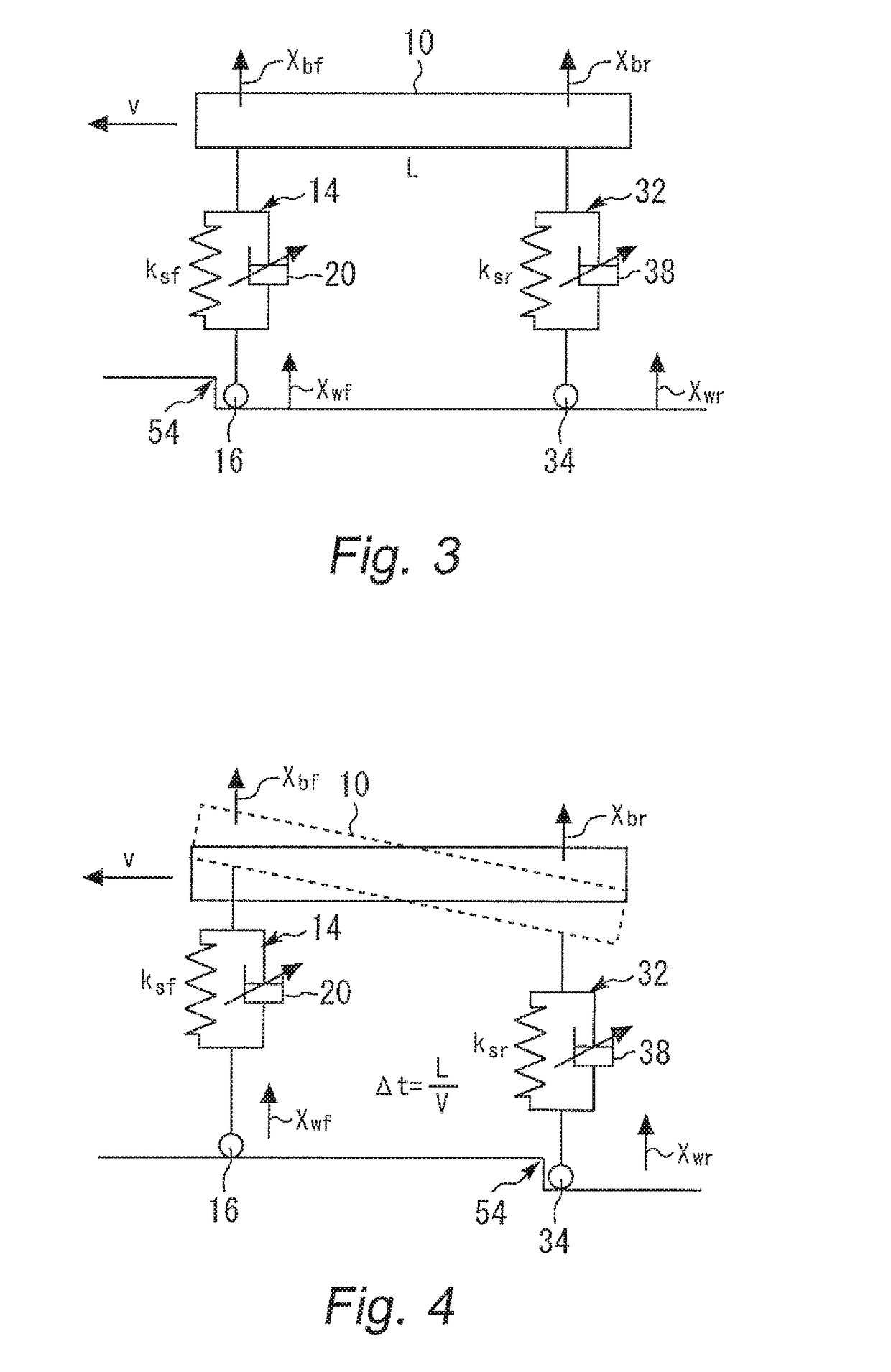
[0088]In the first embodiment described above, the control current for the shock absorber 38 for the rear wheel 34 is switched when the time period Δt=L / v has elapsed after the front wheel 16 reaches the rising point 54 on the road surface. However, the timing for the switching can also be determined by taking a delay time of an actuator or the like into consideration. That is, if there is a delay time Td from the time when the ECU 50 outputs the switching command to the time when the damping coefficient Csr is actually switched, the ECU 50 can output the switching command at a timing when a time period “L / v-Td” has elapsed after the front wheel 16 reaches the rising point 54.

[0089]In the first embodiment described above, the left and right front wheels are not discriminated, and the left and right rear wheels are not discriminated. However, the determination of whether or not the front wheel 16 goes over the rising point 54 and the switching of the damping coefficient Csr regarding...


PUM


Abstract

A vehicle suspension includes a shock absorber whose damping coefficient is variable. A control device includes: a road surface input sensor that generates a first signal corresponding to a vertical movement of each wheel; a sprung mass behavior sensor that generates a second signal corresponding to a vertical movement of a vehicle body at a position of each wheel; and a control unit that controls the damping coefficient. The control unit performs: a normal control that sets the damping coefficient to a hard-side value with regard to a wheel where the second signal indicates occurrence of a sprung mass behavior exceeding a standard; and a rear wheel softening control that sets the damping coefficient regarding a rear wheel to a soft-side value lower than the hard-side value, when determining, based on the first signal, that a rear-wheel-rising-time-point when the rear wheel reaches a rising point on a road surface comes.

Description

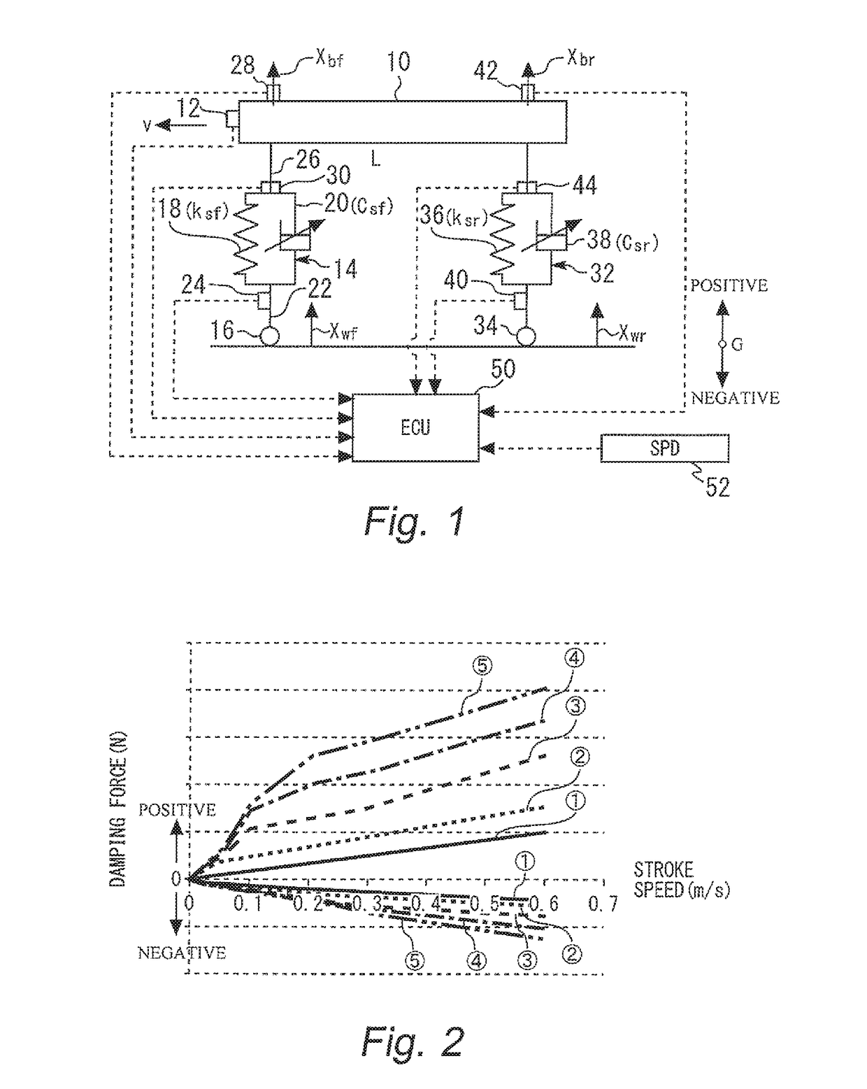
BACKGROUND[0001]Technical Field[0002]The present invention relates to a control device for a vehicle suspension, particularly to a control device for a vehicle suspension capable of changing a damping coefficient.[0003]Background Art[0004]Patent Literature 1 discloses a suspension device that can change, as appropriate, a damping coefficient of a shock absorber provided to each wheel. According to this suspension device, the damping coefficient of the shock absorber of each wheel is controlled in response to a variety of requests. When a front wheel of a vehicle goes over a bump, the damping coefficient of the shock absorber of a rear wheel is set to be a soft-side value until the rear wheel overcomes the bump, regardless of other control requests (see the third embodiment and FIG. 10).[0005]According to the control mentioned above, the damping coefficient of the shock absorber of the rear wheel is surely the soft-side value at a time when the rear wheel goes over a bump after the f...

Claims


Application Information

Patent Timeline
IPC IPC(8): B60G17/0165B60G17/019
CPCB60G17/01908B60G17/0165B60G17/019B60G17/08B60G2401/14B60G2401/21B60G2500/10F16F15/002
Inventor LIU, YANQING
Owner TOYOTA JIDOSHA KK
Learn More