Aerial vehicle

Inactive Publication Date: 2017-06-22
NIPPON SOKEN +1
View PDF0 Cites 28 Cited by
  • Summary
  • Abstract
  • Description
  • Claims
  • Application Information

AI Technical Summary

Benefits of technology

[0009]The overlap between the first rotating regions of the first propellers and the second rotating regions of the second propellers in the direction of the yaw axis of the aerial vehicle and the separation of the first regions and the second regions from each other in the direction of the yaw axis result in a decreased area of projection of the aerial vehicle, as viewed from th

Problems solved by technology

Specifically, when the aerial vehicle is viewed from the front or side thereof, it will result in an increased area of occupation of the aerial veh

Method used


Image

  • Aerial vehicle
  • Aerial vehicle
  • Aerial vehicle

Examples


Example

First Embodiment

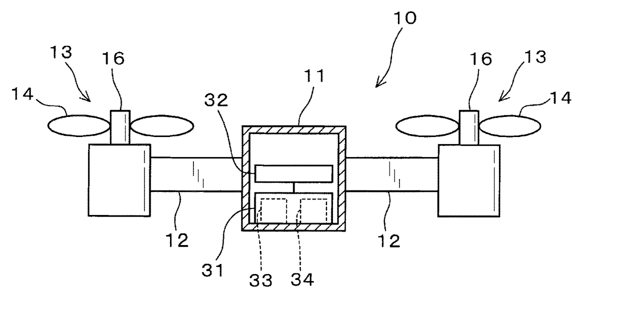
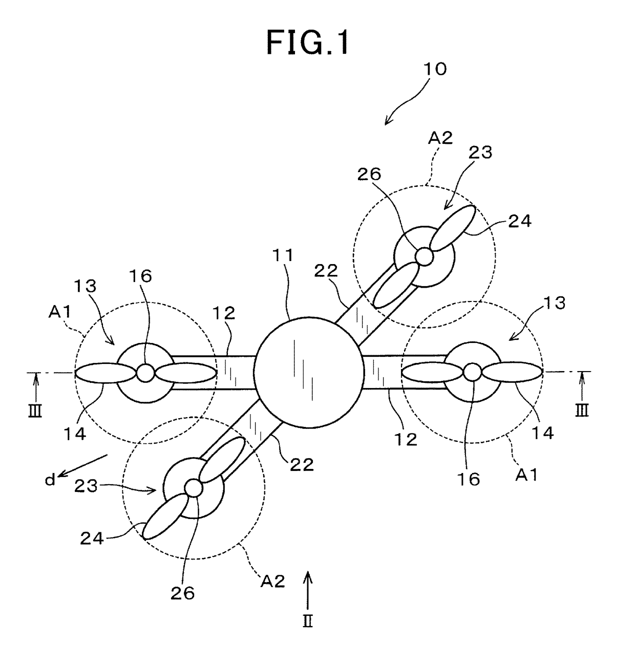
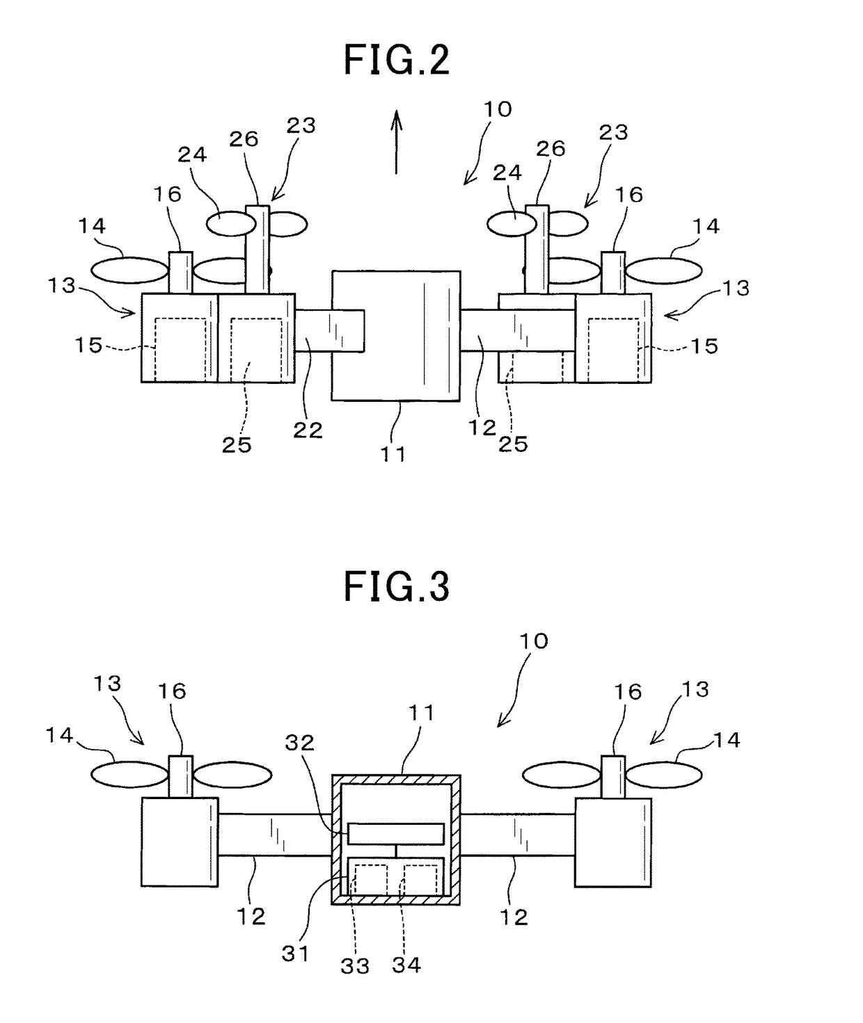
[0023]The aerial vehicle 10, as illustrated in FIGS. 1 to 3, includes the vehicle body 11, the first arms 12, the first thrusters 13, and the first propellers 14. The vehicle body 11 is located at the center of gravity of the aerial vehicle 10. The first arms 12 radially extend from the vehicle body 11 to be symmetrical about the vehicle body 11. The first arms 12 are provided as a pair on the vehicle body 11. Each of the first thrusters 13 is secured to one end of a corresponding one of the first arms 12 which is opposite the other end to which the vehicle body 11 is joined. The first propellers 14 rotate on the first thrusters 13 to produce propulsive power of the aerial vehicle 10. The first thrusters 13 each have the motor 15 as a drive source to rotate the first propeller 14. The torque, as produced by each of the motors 15, is transmitted to one of the first propellers 14 through the first shaft 16.

[0024]The aerial vehicle 10 also includes the second arms 22, t...

Example

Second Embodiment

[0030]FIG. 5 shows the aerial vehicle 10 according to the second embodiment.

[0031]The aerial vehicle 10 is equipped with the drive unit 41. The drive unit 41 is installed inside the vehicle body 11. The drive unit 41 works as an actuator to swivel the first arms 12 and the second arms 22 relative to each other around the yaw axis. Specifically, the drive unit 41 rotates the first arms 12 and the second arms 22 relative to each other in a range from an angular position where the angle which the each of the first arms 12 makes with one of the second arms 22, as indicated by broken lines in FIG. 5, is 90° to an angular position where the each of the first arms 12 makes with one of the second arms 22, as indicated by solid lines in FIG. 5, is less than 90°. The drive unit 41 in the second embodiment is designed to swivel only the second arms 22 about the yaw axis.

[0032]When the first arms 12 and the second arms 22 are oriented so as to be at 90° to each other, and the v...

Example

Third Embodiment

[0034]FIG. 6 shows the aerial vehicle 10 according to the third embodiment.

[0035]The vehicle body 11 is made up of two discrete parts: the first body 51 and the second body 52 which are joined together at the center of a length of the vehicle body 11 extending in the yaw axis of the aerial vehicle 10. The first body 51 has secured thereto the first arms 12 on which the first thrusters 13 are disposed. The second body 52 has secured thereto the second arms 22 on which the second thrusters 23 are mounted. The first body 51 and the second body 52 are rotatable relative to each other at the center of the vehicle body 11 in the lengthwise direction (i.e., the direction of the yaw axis) to orient the first thrusters 12 secured to the first arms 12 and the second thrusters 23 secured to the second arms 22 to be arranged out of alignment with each other in the direction of the yaw axis. Accordingly, the plane including the rotating region A1 of each of the first propellers 1...


PUM


Abstract

An aerial vehicle is provided which includes first thrusters with first propellers and second thrusters with second propellers. Each of the first propellers has a first rotating region in which blades thereof rotate. Similarly, each of the second propellers has a second rotating region in which blades thereof rotate. Each of the first rotating regions is located to overlap one of the second rotating regions, as viewed in a direction of a yaw axis of the aerial vehicle. The first rotating regions are located away from the second rotating regions in the direction of the yaw axis. Such layout of the first and second propellers eliminates physical interference therebetween. The overlap between the first and second propellers results in a decreased cross-sectional area of projection of the aerial vehicle from the front view in a flight direction thereof.

Description

CROSS REFERENCE TO RELATED DOCUMENT[0001]The present application claims the benefit of priority of Japanese Patent Application No. 2015-245265 on Dec. 16, 2015, the disclosure of which is incorporated herein by reference.BACKGROUND[0002]1 Technical Field[0003]The invention relates generally to an aerial vehicle.[0004]2 Background Art[0005]Aerial vehicles commonly known as drones are equipped with a plurality of thrusters to produce propulsive power for ascent. The thrusters of the aerial vehicle are arranged without overlaps of propellers in order to generate an adequate propulsive force. Japanese Patent First Publication No. 2014-240242 teaches thrusters of an aerial vehicle which have propellers which are arranged in two circles. The thrusters have the propellers disposed at intervals away from each other without any physical interference among them.[0006]The layout of the thrusters without any overlap of regions of rotation of the propellers, however, results in an increase in ar...

Claims


Application Information

Patent Timeline
IPC IPC(8): B64C27/08B64C1/30B64C39/02
CPCB64C27/08B64C39/024B64C1/30B64C2201/165B64C2201/108B64C2201/042B64C2201/024B64U10/13B64U30/20B64U80/00B64U50/13B64U10/10B64U50/19
Inventor BABA, HIROYASUKAWASAKI, KOJIMATSUE, TAKENORI
Owner NIPPON SOKEN
Why Eureka
Try Eureka