Hydro pneumatic accumulator with internal leak detection

a pneumatic accumulator and leak detection technology, applied in the direction of actuator accumulators, fluid-pressure actuators, mechanical devices, etc., can solve the problems of internal leakage, primarily from the periphery of the piston, and achieve the effect of reducing the risk of internal leakag

Inactive Publication Date: 2017-06-22
ROTEX MFR & ENGINEERS
View PDF8 Cites 2 Cited by
  • Summary
  • Abstract
  • Description
  • Claims
  • Application Information

AI Technical Summary

Benefits of technology

[0023]When there is no internal leakage of the gas into the liquid chamber or the liquid into the gas chamber, the first cylindrical channel of the gas end cover is free of any gas or liquid, and the first pressure meter as well as the second pressure meter shows a zero reading. When there is a leakage of the gas towards the liquid chamber, the gas first ingresses to the annular hollow ring of the floating piston, then through the hollow tube of the floating piston, fills in the hollow zone of the floater. The floater device attains suspended position and lets the gas fill the first cylindrical channel, the conical channel and the second cylindrical channel. The first pressure meter as well as the second pressure meter shows a low non-zero reading, indicating a gas leak towards or into the liquid chamber. When the gas leakage is rapid such that the gas also reaches the liquid chamber, the outcome is the same, that is, the first pressure meter as well as the second pressure meter shows the low but non-zero reading.

Problems solved by technology

While piston type accumulator has proven to be robust and naturally dampening the pressure spikes encountered in the use, inter-chamber leakage, primarily from periphery of the piston is a known challenge.

Method used


Image

  • Hydro pneumatic accumulator with internal leak detection
  • Hydro pneumatic accumulator with internal leak detection
  • Hydro pneumatic accumulator with internal leak detection

Examples


Embodiment Construction

[0028]The preferred embodiment of present invention is described with the aid of the drawings. Several variations of present invention are possible and therefore the description of the embodiments should not be construed to limit the scope of this invention in any manner.

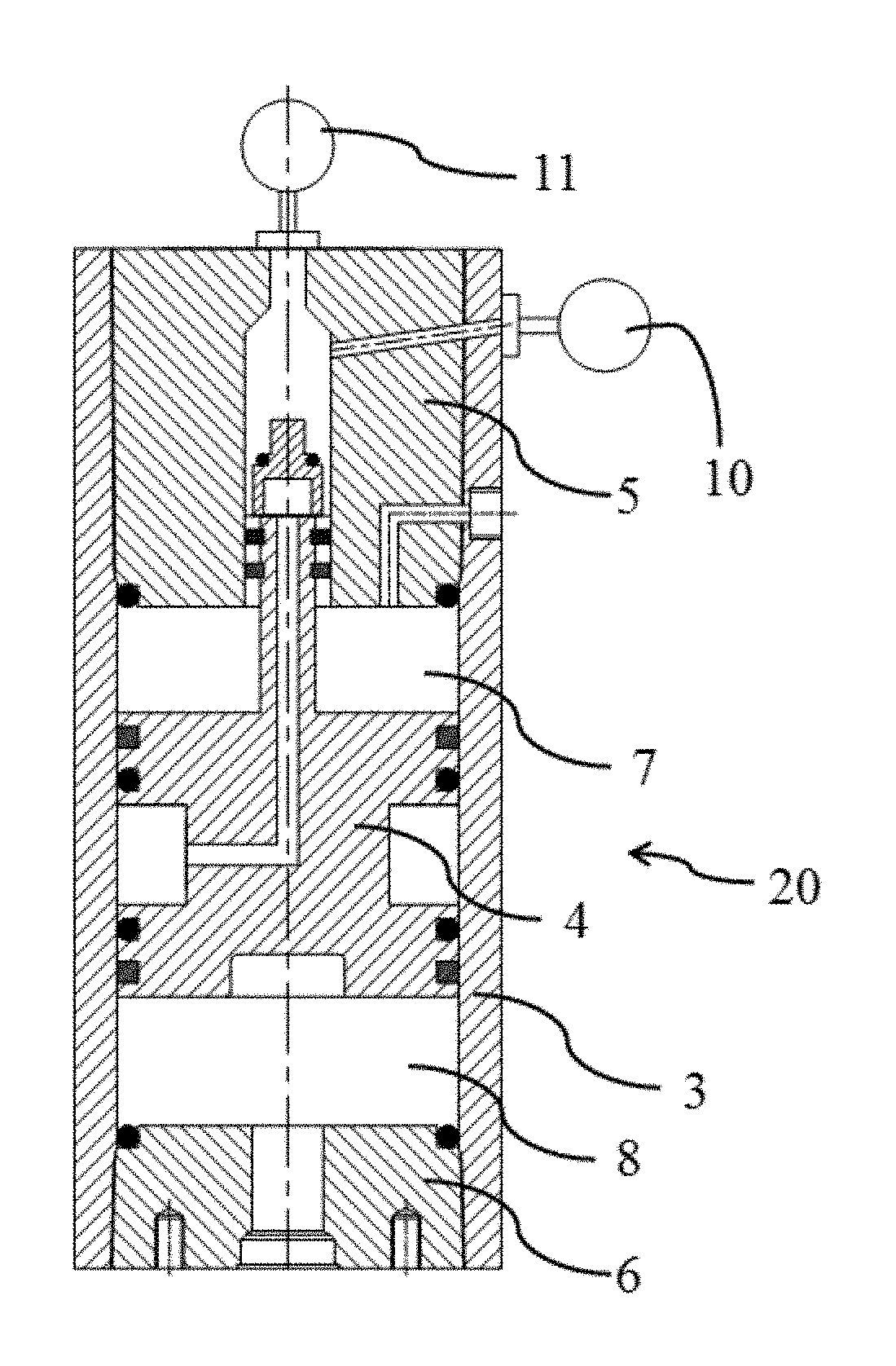
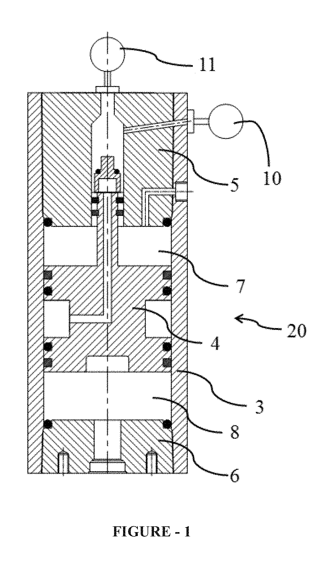
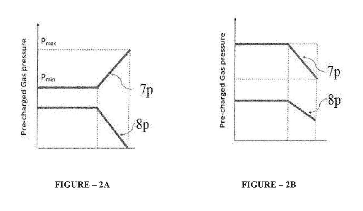
[0029]FIG. 1 shows a piston type hydro pneumatic accumulator (20) with internal leak detection as per present invention. The piston type hydro pneumatic accumulator (20) comprises of a cylindrical barrel (3), a floating piston (4), a gas end cover (5) and a liquid end cover (6). A first pressure meter (10) and a second pressure meter (11) are disposed as shown. The accumulator has a gas chamber (7) and a liquid chamber (8). Generally, the liquid chamber (8) is connected to any point of application. FIG. 2A which shows situation of liquid (8L) leaking into gas chamber (7) causing a rise in a gas pressure (7p) and a fall in a liquid pressure (8p), and FIG. 2B which shows situation of gas (7G) leaking into liquid chamb...


PUM


Abstract

A piston type hydro pneumatic accumulator with internal leak detection, having a gas chamber and a liquid chamber, the piston type hydro pneumatic accumulator comprising a cylindrical barrel, a floating piston, a gas end cover, a liquid end cover, a leakage detection construction having a first cylindrical channel reducing to a conical channel and further reducing to a second cylindrical channel, a floater device, the gas end cover and the liquid end cover hermetically disposed into the cylindrical barrel, a first pressure meter disposed so as to measure a pressure in the first cylindrical channel and a second pressure meter disposed so as to measure the pressure in the second cylindrical channel, the readings in the two pressure meters used for inferring a gas leakage or a liquid leakage. Also deployable a first pressure switch sensing a pressure P1 and a second pressure switch sensing a pressure P2, the output of the first pressure switch and the second pressure switch connected to a programmable logic controller, programmed so as to activate a liquid circuit for topping up of the liquid if P1>P2, activate a gas circuit for re-charging of gas if P1=P2≠0, produce a visual and or an audio signal or a combination thereof, or initiate any other corrective action.

Description

[0001]The following specification particularly describes the invention and the manner in which it is to be performed.FIELD OF INVENTION[0002]This invention relates to Hydro Pneumatic Accumulators. Particularly, the invention relates piston type hydro pneumatic accumulators. More particularly this invention relates to piston type hydro pneumatic accumulators with arrangement to detect inter-fluid leakage.BACKGROUND OF THE INVENTION[0003]A hydro pneumatic accumulator is conceptually a device wherein one fluid under pressure is utilized as potential energy for performing useful work through the medium of another fluid. A hydro pneumatic accumulator is typically used in a hydraulic system for preventing the pressure of a hydraulic fluid, e.g., an oil, from rising excessively or falling suddenly due to temporary accumulating or discharging of oil or any turbulence in the hydraulic system. For example, the accumulator temporarily accumulates oil fed from a pump while a fluid-actuated devi...

Claims


Application Information

Patent Timeline
Patent Type & Authority Applications(United States)
IPC IPC(8): F15B1/24
CPCF15B1/24F15B2201/50F15B2201/312F15B2201/205
Inventor SHAH, AMITKOTHADIA, AJIT
Owner ROTEX MFR & ENGINEERS
Why Eureka
Try Eureka