
Micro-magnetic Detecting Method and Micro-magnetic Detecting Device

a micro-magnetic detection and micro-magnetic technology, applied in the field of detection techniques, can solve the problems of different pipeline inspection methods for buried pipelines without excavation or shutting down the pipeline, and the work flow will certainly affect the normal operation of buried pipelines,

Active Publication Date: 2017-06-22
NINGBO YINZHOU CITAI ELECTRONICS TECH CO LTD
View PDF2 Cites 11 Cited by
  • Summary
  • Abstract
  • Description
  • Claims
  • Application Information

AI Technical Summary

Benefits of technology

The present invention provides a micro-magnetic detecting method and device that can detect surface and internal defects of an object by measuring the magnetic induction intensity from its surface when it remains unchanged. This enhances efficiency, reduces cost, improves adaptability, and performance of the detecting apparatus.

Problems solved by technology

Such work flow will certainly affect the normal operation of the buried pipeline.
Obviously, different pipeline inspection methods for the buried pipeline without excavation or shutting down the pipeline have become an issue that is worth further discussion.
Although sound can be transmitted in metals, ultrasonic wave decays quickly in the air, which is the major drawback of this method.
However, it functions poorly on ferromagnetic materials.
Moreover, the turbulent flow detecting method also requires exciting source, which becomes not applicable when there is no exciting source in certain circumstances.

Method used


Image

  • Micro-magnetic Detecting Method and Micro-magnetic Detecting Device
  • Micro-magnetic Detecting Method and Micro-magnetic Detecting Device
  • Micro-magnetic Detecting Method and Micro-magnetic Detecting Device

Examples


Embodiment Construction

[0073]The following description is disclosed to enable any person skilled in the art to make and use the present invention. Preferred embodiments are provided in the following description only as examples and modifications will be apparent to those skilled in the art. The general principles defined in the following description would be applied to other embodiments, alternatives, modifications, equivalents, and applications without departing from the spirit and scope of the present invention.

[0074]The following applies both the appended drawings and the embodiments to further describe the present invention in detail.

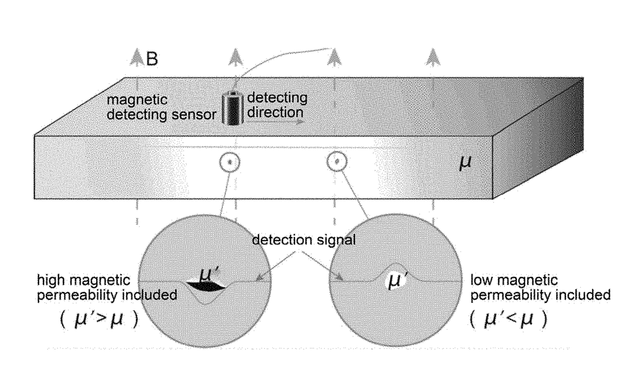
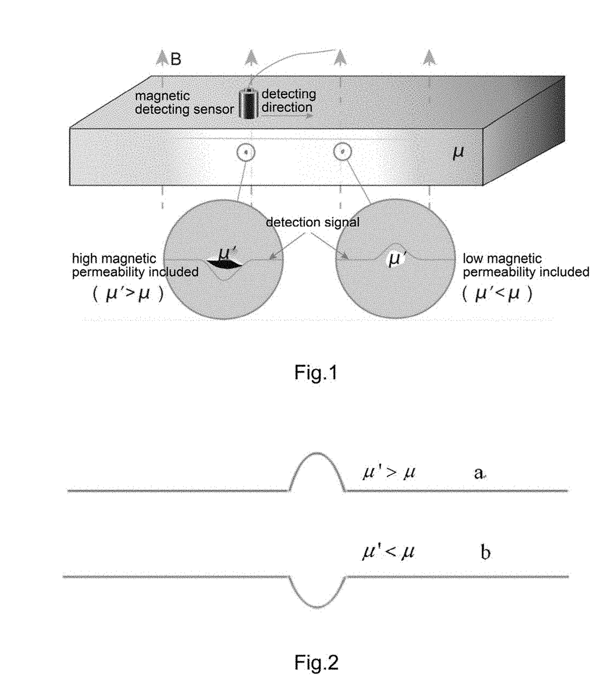
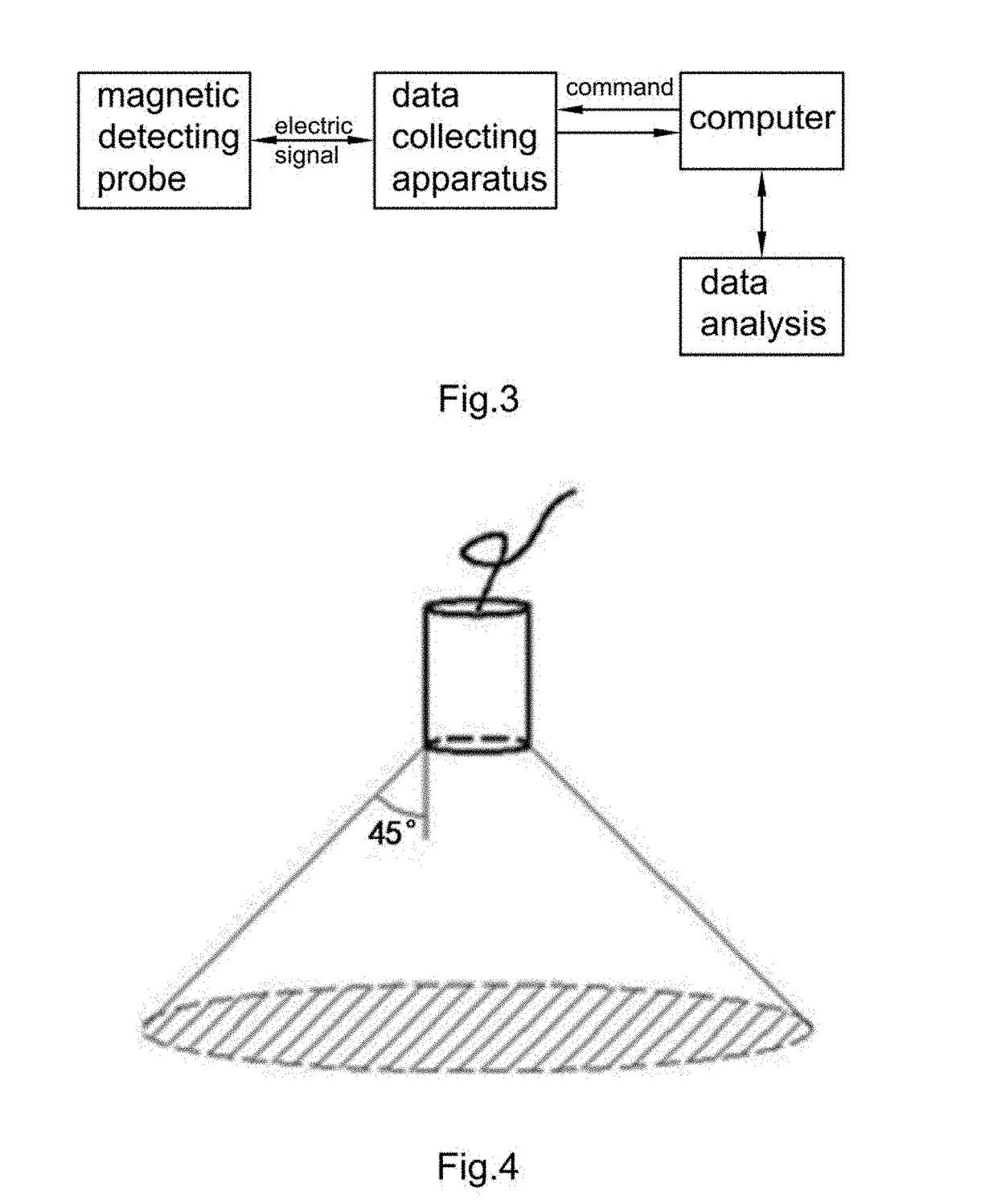
[0075]Micro-magnetic detecting technology is based on a foundation of natural magnetic field, which is a nondestructive detecting technique that applies magnetic signal detector to scan and detect the surface or near-surface of the detected sample to determine the changes of magnetic induction intensities in various directions for determine whether there is a defect on th...


PUM

PropertyMeasurementUnit
diameteraaaaaaaaaa
diameteraaaaaaaaaa
diameteraaaaaaaaaa

Abstract

A micro-magnetic detecting method includes the steps of: detecting a magnetic induction intensity along a first direction on a surface of a detected object to generate a detection signal, determining whether an amplitude of the detection signal is an anomalous value at a first position of the surface of the detected object, wherein the anomalous value is a value which is inconsistent with a linear value of the detection signal at the first position, and the linear value is a value that satisfies a linear relationship of the detection signal, and determining there is a defect at the first position of the detected object in case that the amplitude of the detection signal is the anomalous value. Accordingly, it detects the magnetic induction intensity on the surface of the detected object so as to detect its surface and internal defects when it remains in its original status.

Description

CROSS REFERENCE OF RELATED APPLICATION[0001]This is a non-provisional application that claims priority to international application number PCT / CN2016 / 087008, international filing date Jun. 24, 2016, which claims priority to Chinese application number CN201510422681.5, filing date Jul. 16, 2015, the entire contents of each of which are expressly incorporated herein by reference.NOTICE OF COPYRIGHT[0002]A portion of the disclosure of this patent document contains material which is subject to copyright protection. The copyright owner has no objection to any reproduction by anyone of the patent disclosure, as it appears in the United States Patent and Trademark Office patent files or records, but otherwise reserves all copyright rights whatsoever.BACKGROUND OF THE PRESENT INVENTION[0003]Field of Invention[0004]The present invention relates to field of detecting technique, and in particularly to a micro-magnetic detecting method and a micro-magnetic detecting device for detecting an unde...

Claims


Application Information

Patent Timeline
Patent Type & Authority Applications(United States)
IPC IPC(8): G01N27/82G01R19/04G01R33/12
CPCG01N27/82G01R19/04G01R33/1223G01R33/10G01N27/72
Inventor YU, RUNQIAOZHANG, BINHU, BOXIA, GUISUOCHENG, DONGFANGCHENG, QIANGQIANG
Owner NINGBO YINZHOU CITAI ELECTRONICS TECH CO LTD
Learn More