Light modulation device including dielectric antenna

a dielectric antenna and light modulation technology, applied in the direction of optics, instruments, optical elements, etc., can solve the problems of slow operation response time of such optical modulators and may reach more than several s, and achieve the effect of wide control range of light modulation and small light loss

Active Publication Date: 2017-06-22
SAMSUNG ELECTRONICS CO LTD
View PDF3 Cites 19 Cited by
  • Summary
  • Abstract
  • Description
  • Claims
  • Application Information

AI Technical Summary

Benefits of technology

[0008]One or more exemplary embodiments may provide a light modulation device that modulates light and has small light loss and a wide control range of light modulation.

Problems solved by technology

However, operating response times of such optical modulators are slow and may reach more than several μs according to known methods of driving optical modulators.

Method used


Image

  • Light modulation device including dielectric antenna
  • Light modulation device including dielectric antenna
  • Light modulation device including dielectric antenna

Examples


Embodiment Construction

[0065]Reference will now be made in detail to exemplary embodiments, examples of which are illustrated in the accompanying drawings, wherein like reference numerals refer to like elements throughout. In this regard, the exemplary embodiments may have different forms and should not be construed as being limited to the descriptions set forth herein. Accordingly, the exemplary embodiments are merely described below, by referring to the figures, to explain aspects. Expressions such as “at least one of,” when preceding a list of elements, modify the entire list of elements and do not modify the individual elements of the list.

[0066]Hereinafter, exemplary embodiments will be described with reference to the accompanying drawings. Throughout the drawings, each element may be exaggerated in size for clarity and convenience of explanation. Accordingly, the exemplary embodiments are merely illustrative, and various modifications may be possible from the exemplary embodiments.

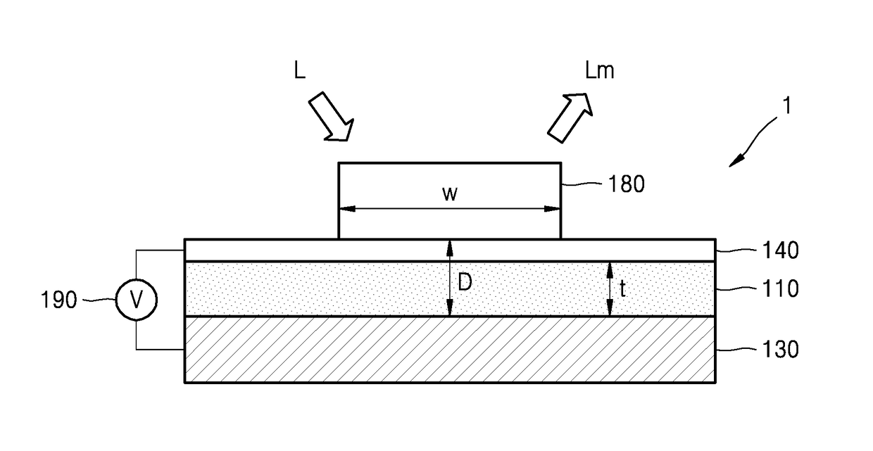
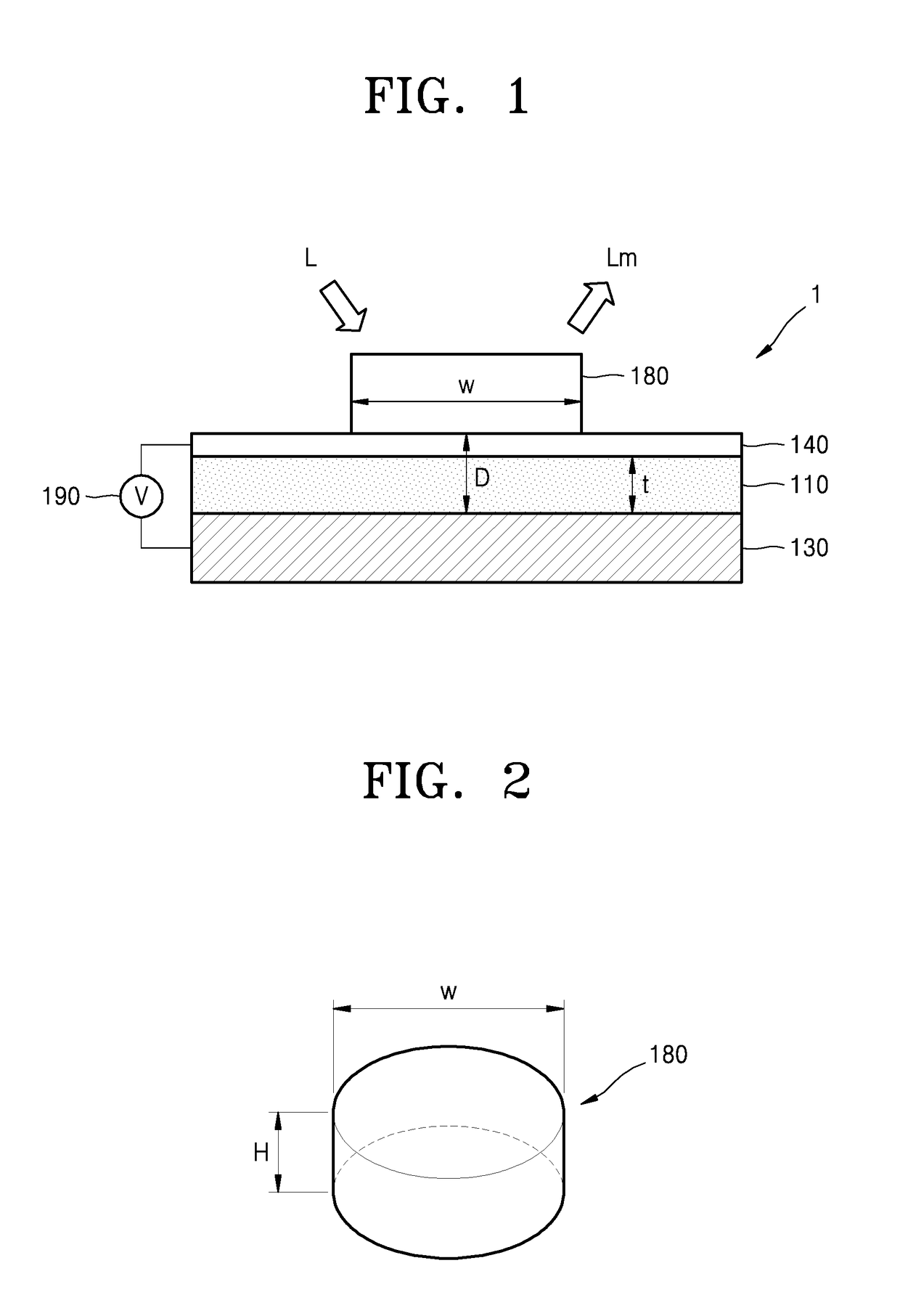
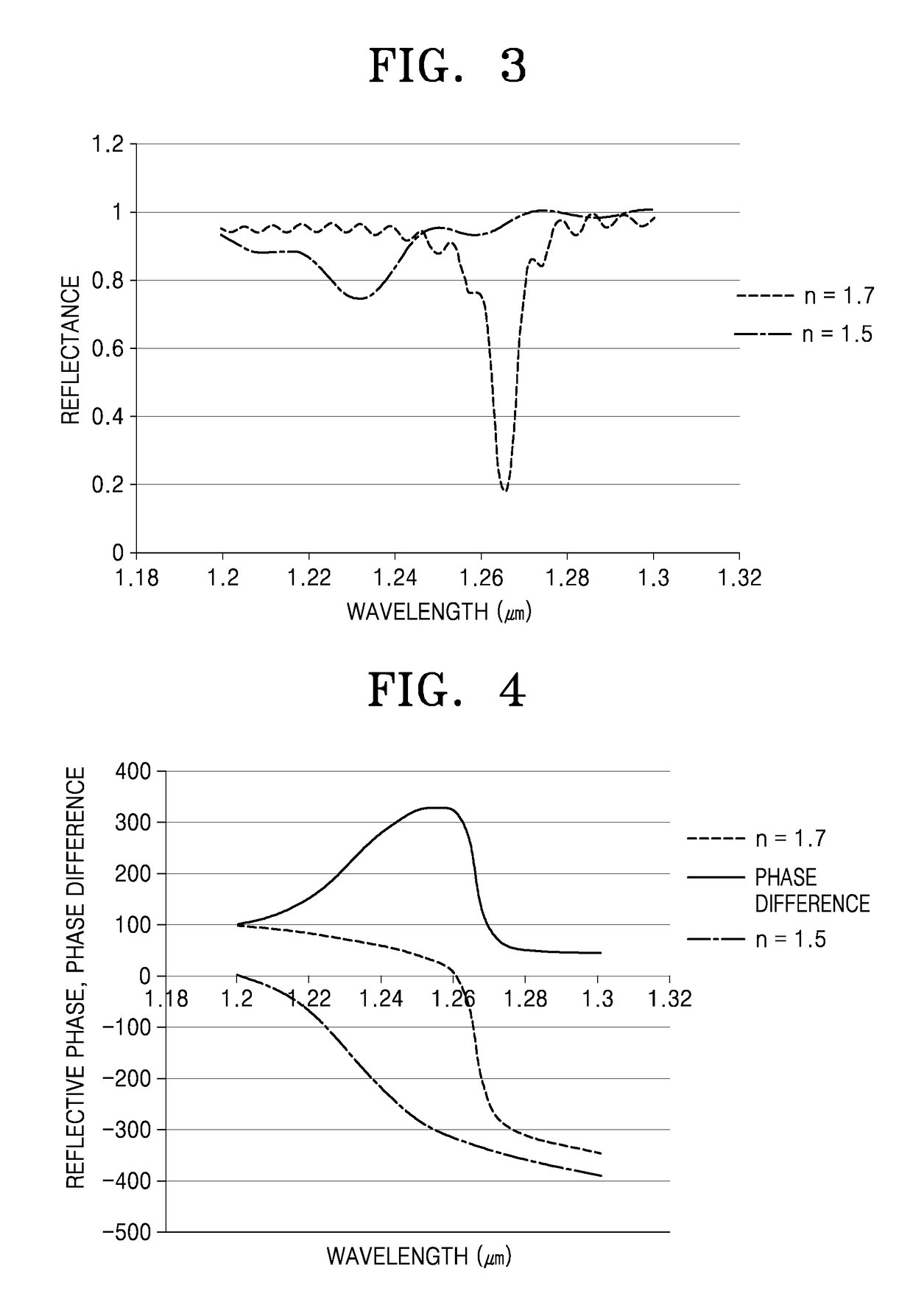
[0067]In a layer s...


PUM

PropertyMeasurementUnit
dielectric constantaaaaaaaaaa
refractive indexaaaaaaaaaa

Abstract

A light modulation device includes a dielectric antenna and a refractive-index-variable layer which faces the dielectric antenna and comprises a material having a refractive index that changes according to a signal. A light may be modulated, since resonance characteristics of the dielectric antenna are controlled according to a refractive-index change of the refractive-index-variable layer.

Description

CROSS-REFERENCE TO RELATED APPLICATION[0001]This application claims the benefit of Korean Patent Application No. 10-2015-0181078, filed on Dec. 17, 2015, in the Korean Intellectual Property Office, the disclosure of which is incorporated herein in its entirety by reference.BACKGROUND[0002]1. Field[0003]Apparatuses and methods consistent with exemplary embodiments relate to light modulation devices that modulate light.[0004]2. Description of the Related Art[0005]Optical elements that change transmission, reflection, polarization, phase, intensity, and path of incident light have been used in various optical devices. Optical modulators used in optical systems have various structures for controlling these properties in a desired manner.[0006]For example, anisotropic liquid crystals and microelectromechanical system (MEMS) structures, using fine mechanical movement to block light or control reflection elements, as well as other elements, have been widely used in typical optical modulato...

Claims


Application Information

Patent Timeline
Patent Type & Authority Applications(United States)
IPC IPC(8): G02B5/00G02F1/29G02F1/19
CPCG02B5/008G02F1/292G02F1/19G02F1/0102G02F1/0121G02F1/2955G02F2202/30G02F2203/12
Inventor LEE, DUHYUNKIM, SUNILSHIN, CHANGGYUNKIM, JUNGWOOLEE, CHANG BUM
Owner SAMSUNG ELECTRONICS CO LTD
Why Eureka
Try Eureka