
Quarter-wave plate, and optical pickup device

a pickup device and quarter-wave plate technology, applied in the direction of optical beam sources, polarising elements, instruments, etc., can solve the problems of wave plate, wave plate, wave plate, etc., and achieve the effect of high transmittance, easy processing, and large siz

Inactive Publication Date: 2009-08-06
KONICA MINOLTA INC
View PDF0 Cites 3 Cited by
  • Summary
  • Abstract
  • Description
  • Claims
  • Application Information

AI Technical Summary

Benefits of technology

[0022]According to the quarter-wave plate of the present invention, a structural period of the ridge and trough periodic structure can provide relatively large size, easy processability, uniform phase difference characteristics within a broad wavelength band, and high transmittance.
[0023]According to the optical pickup device of the present invention, even when the quarter-wave plate uses plural wavelengths which are different greatly from each other, the optical pickup device includes a quarter-wave plate with uniform phase difference characteristics and with high transmittance for each wavelength, developed in a broad wavelength band. Thereby, it is possible to obtain an optical pickup device with smaller loss of light and high light utilization efficiency.

Problems solved by technology

However, if the structural period is greater than a wavelength of a light flux to be used, form birefringence does not come into effect.
Further, if a structural period is close to the wavelength, undesirable diffraction is caused by the ridge and trough periodic structure, though the form birefringence comes into effect, which makes it difficult to obtain a high zeroth-order light transmittance.
However, a wave plate having dimensions of the structural period like that in the aforesaid Patent Document 1, for example, requires extremely difficult processing.
However, in recent years, there is required an optical disc device capable of coping with three types of optical discs, representing, for example, 405 nm used for a high density optical disc, 650 nm used for DVD and 780 nm used for CD, and it is not easy to secure uniform phase-difference characteristics in a broader wavelength band including the wavelengths.

Method used


Image

  • Quarter-wave plate, and optical pickup device
  • Quarter-wave plate, and optical pickup device
  • Quarter-wave plate, and optical pickup device

Examples


examples

[0063]Next, the invention will be explained more specifically as follows, referring to the example, to which, however, the invention is not limited by the explanation.

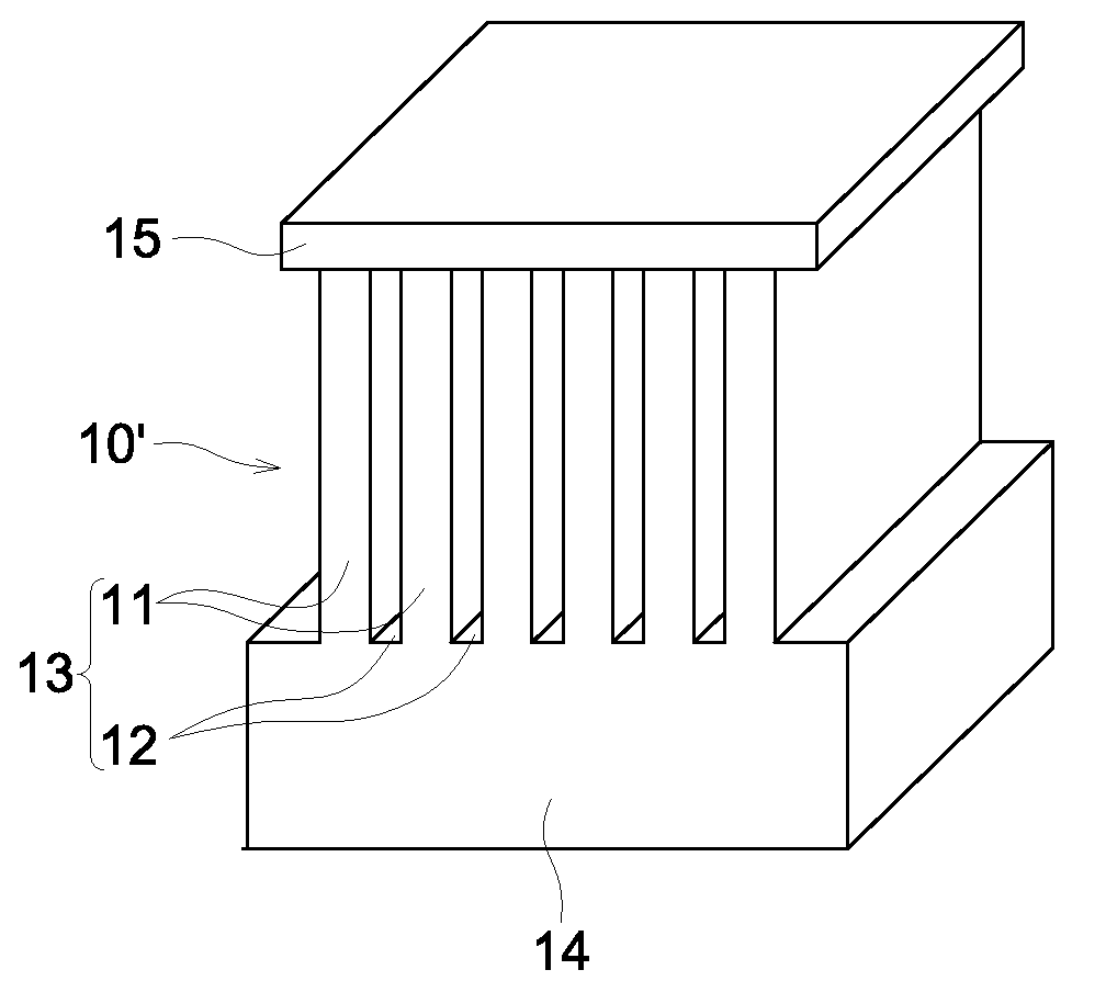
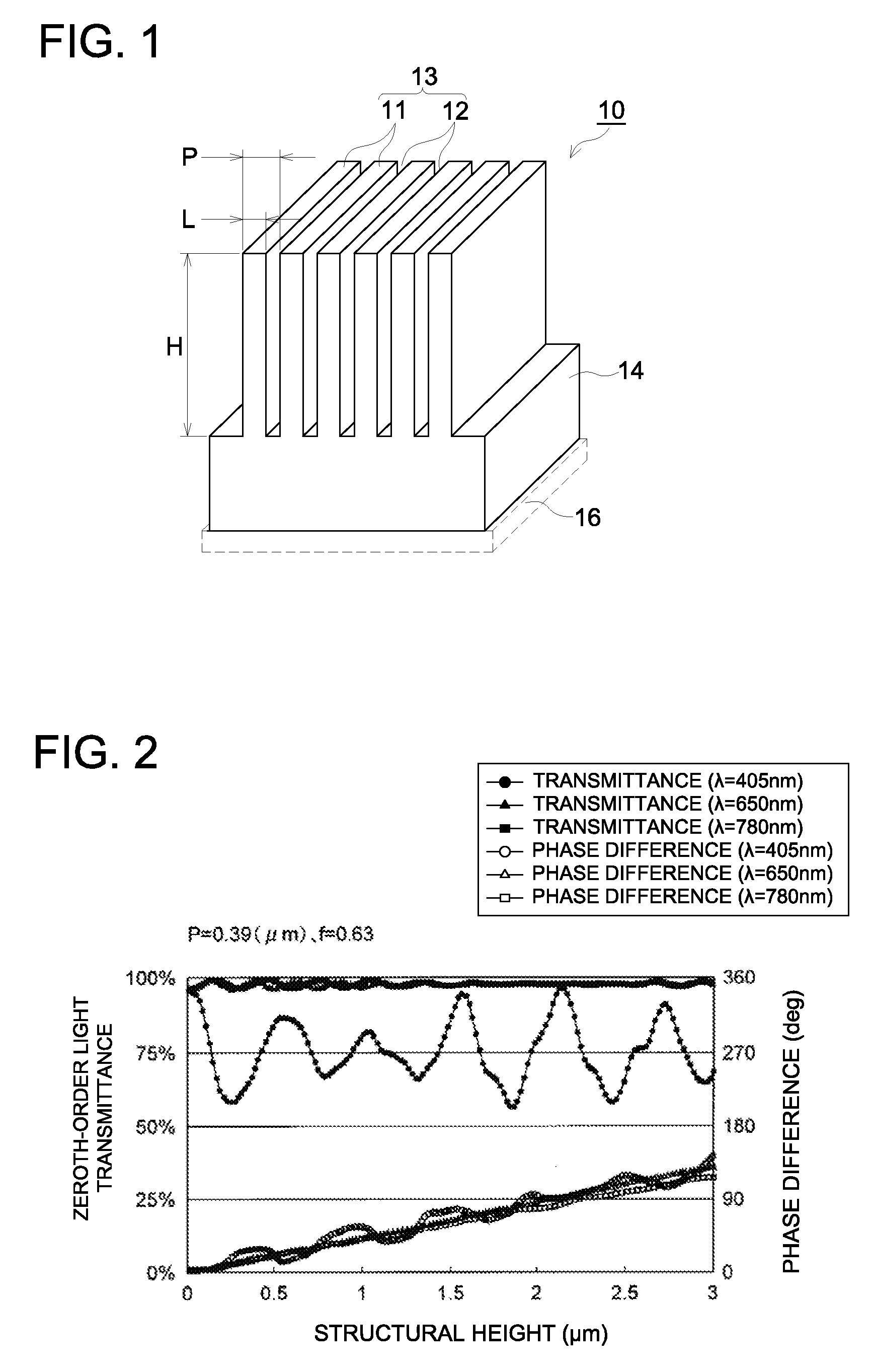
[0064]Wavelength plates grouped into Examples 1-5 and Comparative Examples 1-5 have respective structural dimensions (see FIG. 1) such as structural period P, filling factor f (=L / P) and structural height H which are shown in the following Table 1. Each group was evaluated in terms of transmittance of the zeroth-order light and of phase difference.

[0065]ZEONEX (made by ZEON Corporation) was used as a resin material of the wavelength plate for each of Examples 1-5 and Comparative Examples 1-5, and refractive indexes thereof were as follows.

[0066]n405=1.525 (for wavelength 405 nm)

[0067]n650=1.506 (for wavelength 650 nm)

[0068]n780=1.505 (for wavelength 780 nm)

TABLE 1ExpressionPHΦ405Φ650Φ780Overall(1)*1[μm]f[μm]T405T650T780[deg][deg][deg]judgment*2Example 1◯0.390.632.0890.83%97.45%97.51%89.1391.4980.25◯Example 2◯0.320.722....


PUM

PropertyMeasurementUnit
light transmittanceaaaaaaaaaa
wavelengthsaaaaaaaaaa

Abstract

A quarter-wave plate includes a base member including a ridge and trough periodic structure with a structural period of λmin / 2<P<λmin arranged on one side of the base member, where λmin is the minimum wavelength among the wavelengths of a plurality of light fluxes which pass the quarter-wave plate. In the quarter-wave plate, refractive index of a ridge portion of the ridge and trough periodic structure for the wavelength λmin and a light transmittance have predetermined values. The ridge and trough periodic structure satisfies the predetermined condition relating to the structural height and the structural width of the ridge portion.

Description

TECHNICAL FIELD[0001]The present invention relates to a form birefringence quarter-wave plate having a ridge and trough periodic structure on one side of a base member, and to an optical pickup device including the quarter-wave plate.BACKGROUND ART[0002]The following Patent Document 1 proposes a wave plate that can be used in common for two light fluxes each having a different wavelength, through form birefringence. According to this Patent Document 1, this wave plate is formed through a microscopic periodic structure whose size is a half or less of a wavelength of a target light flux, and the wave plate has the form birefringence that changes the state of polarization of two light fluxes each having a different wavelength, thereby, a wave plate capable of coping with two wavelengths such as, for example, 405 nm and 660 nm can be realized. The microscopic periodic structure whose structural period is 200 nm, duty ratio is 0.64 and structural height is 6000 nm is described in the exa...

Claims


Application Information

Patent Timeline
Patent Type & Authority Applications(United States)
IPC IPC(8): G11B7/135G02B5/30G11B7/125
CPCG02B5/1871G02B5/3083G11B2007/0006G11B7/1367G11B7/1275
Inventor SAITO, MAKIKOMASUDA, OSAMU
Owner KONICA MINOLTA INC
Learn More