Eureka AIR delivers breakthrough ideas for toughest innovation challenges, trusted by R&D personnel around the world.

Liquid ejecting apparatus

Active Publication Date: 2017-06-29
SEIKO EPSON CORP
View PDF1 Cites 2 Cited by
  • Summary
  • Abstract
  • Description
  • Claims
  • Application Information

AI Technical Summary

Benefits of technology

The invention provides a liquid ejecting apparatus that can appropriately receive liquid ejected onto an area outside the medium. The apparatus has two receiving portions: one for receiving waste liquid and one for receiving liquid introduced through preliminary ejection. The second receiving portion has a larger area open to the atmosphere than the first receiving portion, which helps decrease the amount of waste liquid and allows for a longer lifespan or a smaller size of the waste liquid containing chamber. The second receiving portion is also located on the medium support, which prevents the apparatus from increasing in size. Additionally, the region where liquid is received in the second receiving portion can be sequentially changed during preliminary ejection to promote efficient evaporation.

Problems solved by technology

Accordingly, if every preliminary ejection is performed to the ink receiving portion and the suctioning is performed in the same manner every time, a problem arises that the suctioning of ink may be insufficient or excessive.
In particular, when suctioning of ink is insufficient, ink ejected by preliminary ejection may not be fully received by the ink receiving portion.
This problem is not limited to printers that performs printing by ejecting ink.
In general, the same problem may occur in liquid ejecting apparatuses that eject liquid onto a medium and an area outside a medium.

Method used


Image

  • Liquid ejecting apparatus
  • Liquid ejecting apparatus
  • Liquid ejecting apparatus

Examples


Embodiment Construction

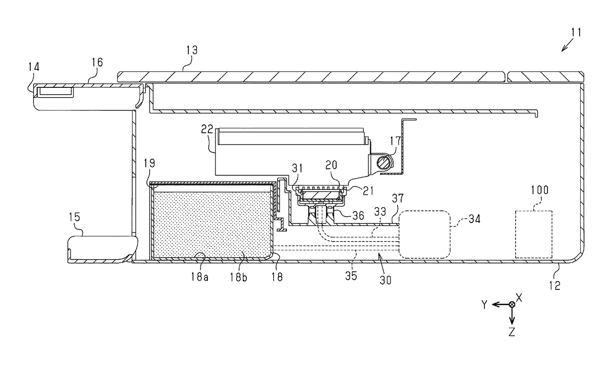
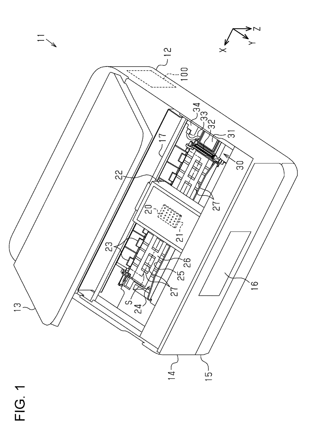
[0028]With reference to the drawings, an embodiment of a liquid ejecting apparatus will be described. The liquid ejecting apparatus is an ink jet printer that performs recording (printing) by ejecting ink which is an example of liquid onto a medium such as a paper sheet.

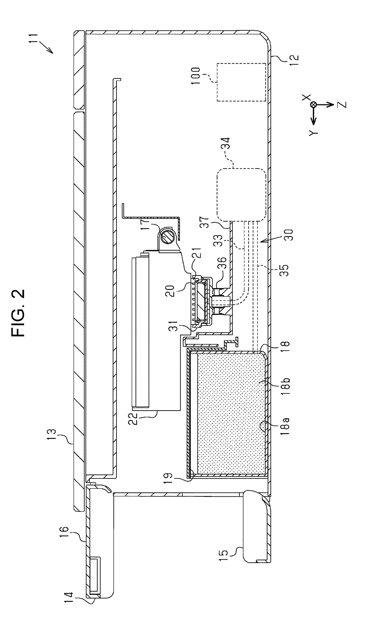
[0029]As shown in FIG. 1, a liquid ejecting apparatus 11 includes a rectangular box-shaped housing 12, and an openable lid 13, an openable panel 14 and an openable cover 15 which are rotatably mounted on the housing 12. The openable lid 13 is mounted on an upper side of the housing 12 with a rotation shaft of the openable lid 13 being located close to a rear side of the housing 12. Accordingly, the openable lid 13 is configured to rotate about the rear end by a predetermined angle so as to move between a close position shown in FIG. 2 and an open position shown in FIG. 1.

[0030]The openable panel 14 mounted on a front side of the housing 12 is configured to rotate about the upper end by substantially 90 degrees so as ...


PUM


Abstract

A liquid ejecting apparatus includes a liquid ejecting head configured to eject liquid; a control unit that makes the liquid ejecting head execute a plurality of types of preliminary ejection, which are ejection of liquid onto a medium and ejection of liquid onto an area outside the medium; and a plurality of receiving portions configured to receive liquid ejected by preliminary ejection, wherein the control unit changes the receiving portion that receives liquid ejected by preliminary ejection depending on the types of preliminary ejection.

Description

BACKGROUND[0001]1. Technical Field[0002]The present invention relates to liquid ejecting apparatuses such as printers.[0003]2. Related Art[0004]Liquid ejecting apparatuses include an ink jet printer that performs printing by ejecting ink from nozzles. In such a printer, preliminary ejection, which is ejection for discharging ink in the nozzle, may be performed in order to prevent or eliminate clogging of nozzles. Moreover, as disclosed in JP-A-2009-39982, the printer may be configured to receive ink ejected by preliminary ejection in an ink receiving portion when ink is ejected onto an area outside a paper sheet during printing performed to the edge of the paper sheet without leaving a margin, and to suction the received ink from the ink receiving portion so as to store in a waste ink tank.[0005]In preliminary ejection, a discharge amount of liquid varies depending on the purpose or timing of ejection. Accordingly, if every preliminary ejection is performed to the ink receiving port...

Claims


Application Information

Patent Timeline
IPC IPC(8): B41J2/045
CPCB41J2/04586B41J2/04505B41J2/1721B41J2/1728B41J2/16523B41J2/16526B41J2002/16573B41J2/16508
Inventor SHIMAZU, MASAMITSUHIZAWA, SHUNICHI
Owner SEIKO EPSON CORP
Why Eureka
Eureka Blog
Learn More