Lighting arrangement and method for constructing a lighting arrangement

a technology of lighting arrangement and lighting arrangement, which is applied in the direction of fixed installation, lighting and heating apparatus, lighting support devices, etc., can solve the problems of disturbing or unattractive direct light source, and achieve the effect of simple and flexible construction and high flexibility

Active Publication Date: 2017-06-29
H4X
View PDF8 Cites 1 Cited by
  • Summary
  • Abstract
  • Description
  • Claims
  • Application Information

AI Technical Summary

Benefits of technology

[0038]In one embodiment, the method furthermore comprises adjusting the light-providing device by sliding displacement and/or rotation of the light-providing device on the housing. The adjustment can thus take place in a particularly simple and flexible manner.
[0039]In a development of the method, the introduction of the light-providing device into the interior, the coupling thereof to the housing and the positioning of the light-provi

Problems solved by technology

Depending on the direction of observation, an observer located in the room may, however, be blinded by conventi

Method used


Image

  • Lighting arrangement and method for constructing a lighting arrangement
  • Lighting arrangement and method for constructing a lighting arrangement
  • Lighting arrangement and method for constructing a lighting arrangement

Examples


first embodiment

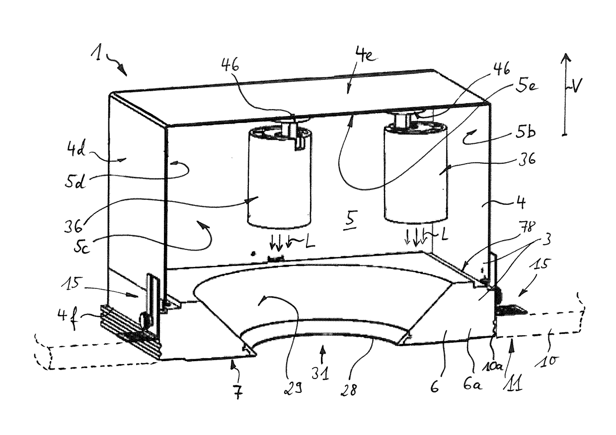
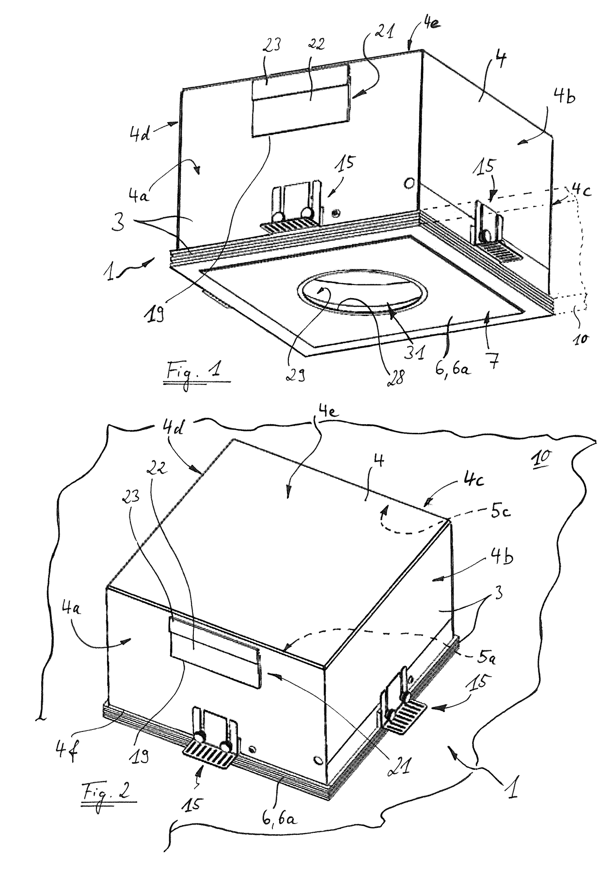
[0066]FIG. 1 shows a lighting arrangement 1 according to the invention. The lighting arrangement 1 has a housing 3, which is formed with a box-like housing part 4 and a plate-like element 6. The housing part 4 is cuboidal and has wall portions 4a to 4d and a top portion 4e, so the housing part 4 is substantially closed on five sides. In the region of the sixth side, in FIG. 1 the base side of the housing part 4, the housing part 4 is open, in other words has an open end 4f. The sixth side of the housing part 4 is closed by the element 6 coupled to the housing part 4 and arranged in the region of the open end 4f. The element 6 and the housing part 4 can be fastened to one another in a suitable manner for this purpose.

[0067]The housing part 4 is configured as a sheet metal part and, for example, is manufactured from steel sheet. On the other hand, the element 6 is configured with an opaque body 6a, the body 6a being configured as a plaster part. The element 6 may, for example, be whit...

third embodiment

[0088]FIG. 13 shows the element 6 of the lighting arrangement 201 with the housing part 4 removed. In addition, the holding means 15 are shown. Except for the shape of the cutout 228 and the region 229, the elements 6 of the lighting arrangements 1 and 101 are also configured in accordance with FIG. 13. The element 6 has a shoulder 8 on the outside, on which, in the assembled state of the housing 3, an edge of the housing part 4 comes to rest in the region of the open end 4f. The edge of the housing part 4 in the region of the open end 4f is suitably formed in a corresponding manner. Furthermore, the body 6a of the element 6 is equipped with a peripheral recessed area 78, which forms a peripheral step in the peripheral direction around the entire element 6 and therefore surrounds the light outlet region 31 in the peripheral direction. The base face of the recessed area 78 is designated 78a and the side face facing outwardly is designated 78b. Both the shoulder 8 and the recessed ar...

second embodiment

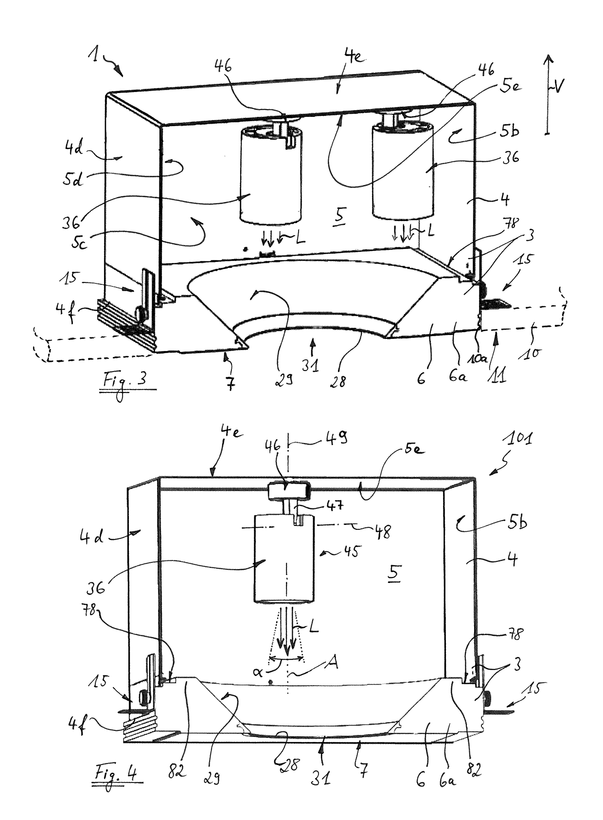
[0092]To be able to supply each of the light-providing devices 36 with electrical current, provided for each of the light-providing devices 36 is a supply line 85, which is configured as an electrical cable. To allow connection to the mains, facilitated by additional devices such as, for example, a transformer 91 and switching and / or control devices, not shown in the figures and provided as required, each of the supply lines 85 is guided out of the interior 5 through the opening 19, which is covered by the cable brush 21. By way of example, this is shown in FIGS. 14 and 15 in two variants of the second embodiment, the supply line(s) 85 also being able to be arranged in an analogous manner in the other embodiments described here. While FIGS. 14 and 15 in each case only show one light-providing device 36, it is obvious that supply lines 85 can be arranged in a similar manner for further light-providing devices 36.

[0093]The supply line 85 is configured in such a way that it can be magn...


PUM


Abstract

A lighting arrangement has a housing having an interior and a light outlet region, and at least one light-providing device. The light-providing device is configured such that it can be arranged within the interior to emit light during operation through the light outlet region to the outside. The light-providing device can be coupled to the housing and can be freely positioned at least within one region of the interior. A second lighting arrangement has a housing having an interior and a light outlet region, the housing having an opening, which is set up to guide at least one line through the opening out of the interior. The second lighting arrangement has at least one brush, which is provided with hairs or fibres or bristles, which are arranged in the opening and/or cover the opening at least in portions.

Description

FIELD OF THE INVENTION[0001]The invention relates to lighting arrangements and to a method for constructing a lighting arrangement.TECHNICAL BACKGROUND[0002]Both in private living spaces and in offices, exhibition spaces, salesrooms and many other premises, an attempt is frequently made to light in a targeted manner a specific region of the room or a plurality of specific regions of the room, articles located in the room, objects hanging on a wall of the room or architectural features of the room. Spotlights fastened, for example, to a ceiling of the room are often used in a conventional manner for this purpose and are oriented to the desired region of the room or the desired object. Depending on the direction of observation, an observer located in the room may, however, be blinded by conventional spotlights of this type or may at least find the directly visible light source unattractive or disturbing.[0003]An improved lighting arrangement is to be proposed, which at least substanti...

Claims


Application Information

Patent Timeline
IPC IPC(8): F21S8/02F21V21/096F21V14/02F21V15/01
CPCF21S8/026F21V14/02F21V21/096F21V15/01F21V17/02F21V17/105F21V21/04F21V21/14F21V23/002H02G3/20
Inventor HIERZER, ANDREAS
Owner H4X
Why Eureka
Try Eureka