High-Resolution Scanning Microscopy

a scanning microscopy, high-resolution technology, applied in the direction of microscopes, instruments, bundled fibre light guides, etc., can solve the problem of cross talk interference, achieve the effect of reducing radiation intensity-dependent cross talk between adjacent pixels of the detector array, reducing and/or eliminating the residual inaccuracy, and maximising the resolution

Active Publication Date: 2017-06-29
CARL ZEISS MICROSCOPY GMBH
View PDF1 Cites 5 Cited by
  • Summary
  • Abstract
  • Description
  • Claims
  • Application Information

AI Technical Summary

Benefits of technology

The invention allows for a faster and more affordable way to do high-resolution microscopy using the LSM method. This opens up a wider range of applications for this technology.

Problems solved by technology

In highly sensitive detector arrays it is known that when adjacent pixels exhibit large differences in the intensity of radiation, they show interference due to cross talk.

Method used


Image

  • High-Resolution Scanning Microscopy
  • High-Resolution Scanning Microscopy
  • High-Resolution Scanning Microscopy

Examples


Embodiment Construction

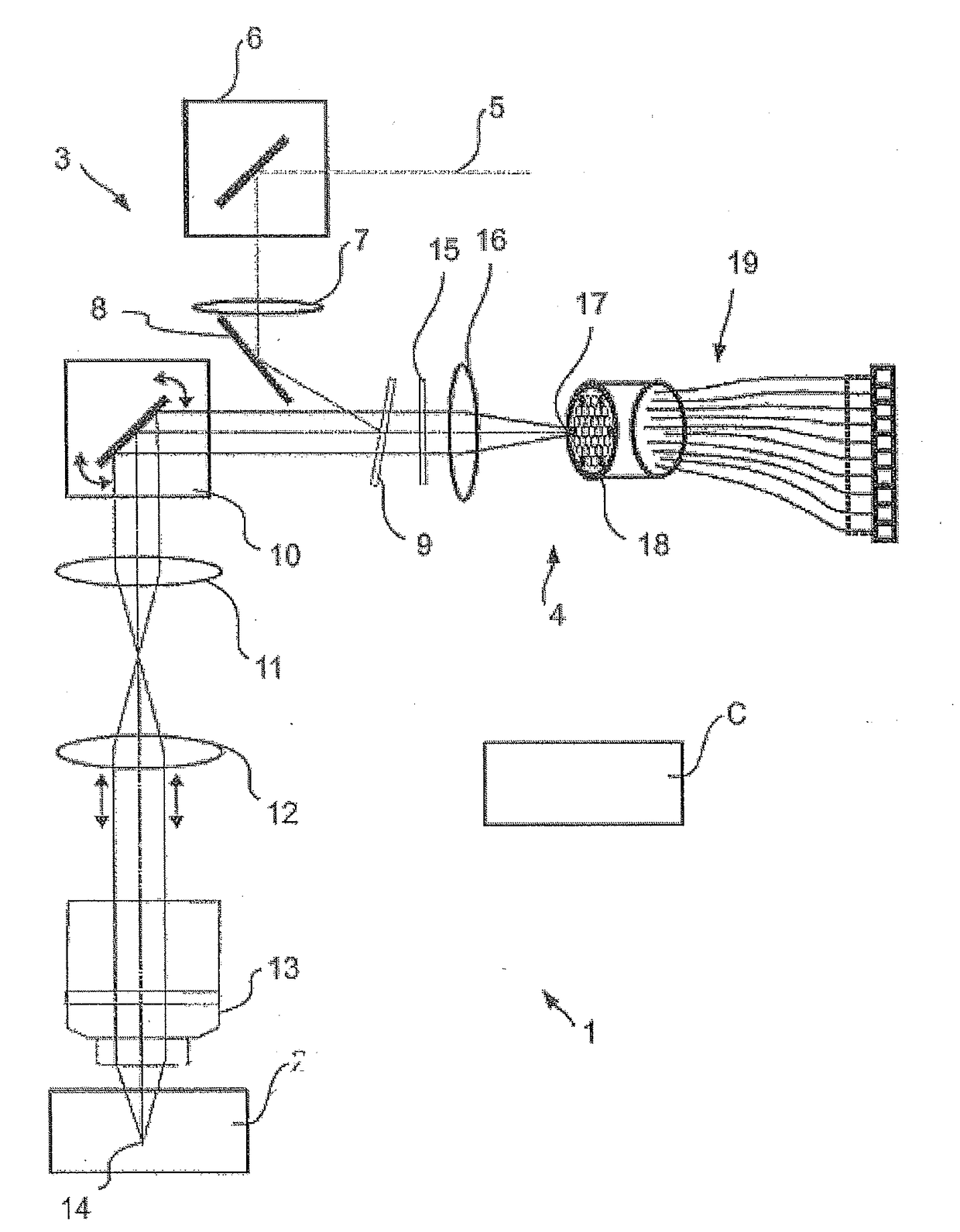
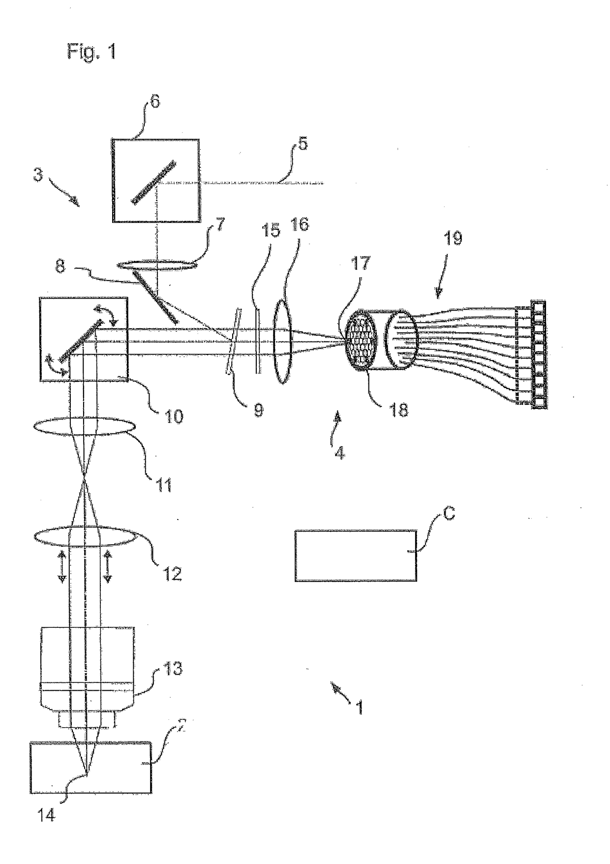
[0042]FIG. 1 shows in schematic form a laser scanning microscope 1, which is designed for microscopying a sample 2. The laser scanning microscope 1 (hereinafter also referred to by the acronym LSM) is controlled by means of a control device C and has an illumination beam path 3 as well as an imaging beam path 4. The illumination beam path illuminates a spot in the sample 2, and the imaging beam path 4 images this spot in a diffraction limited manner for detection. The illumination beam path 3 and the imaging beam path 4 share a plurality of elements. However, this is no more mandatory than a scanned spot illumination of the sample 2, which could also be wide-field illuminated.

[0043]In the case of a laser scanning microscope 1 the sample 2 is illuminated by means of a provided laser beam 5, which is coupled in by means of a deflecting mirror 6, which does not go beyond what is operationally necessary, and a lens 7 onto a mirror 8. The mirror 8 ensures that the laser beam 5 falls onto...


PUM

PropertyMeasurementUnit
fluorescenceaaaaaaaaaa

Abstract

In a microscope for high resolution scanning microscopy of a sample, said microscope comprising—an illumination device for illuminating the sample, —an imaging device for scanning at least one point spot or line spot across the sample and for imaging the point spot or line spot into a diffraction-limited, stationary single image with magnification into a detection plane, —a detector device for detecting the single image in the detection plane for different scanning positions with a spatial resolution, which, taking into consideration the magnification, is at least twice as high as a full width at half maximum of the diffraction-limited single image, —an evaluation device for evaluating a diffraction pattern of the single image for the scanning positions from data of the detector device and for generating an image of the sample, said image having a resolution that is increased beyond the diffraction limit, provision is made for—the detector device to have a detector array, which has pixels and is larger than the single image, and—a non-imaging redistribution element, which is disposed upstream of the detector array and distributes the radiation from the detection plane in a non-imaging manner among the pixels of the detector array.

Description

RELATED APPLICATIONS[0001]The present application is a continuation application of U.S. National Stage application Ser. No. 14 / 373,602 filed on Jul. 21, 2014, which depends from International PCT Application No. PCT / EP2013 / 053980, which was filed on Feb. 27, 2013, and the present application further claims priority benefit of U.S. Provisional Application No. 62 / 025,643 filed on Jul. 17, 2014, the contents of each are hereby incorporated by reference in their entirety.FIELD OF THE INVENTION[0002]The invention relates to a microscope for high resolution scanning microscopy of a sample, said microscope including an illumination device for illuminating the sample, an imaging device for scanning a point spot or line spot across the sample and for imaging the point spot or line spot into a diffraction-limited, stationary single image with magnification into a detection plane. Also included is a detector device for detecting the single image in the detection plane for different scanning po...

Claims


Application Information

Patent Timeline
Patent Type & Authority Applications(United States)
IPC IPC(8): G02B21/36G02B6/08G02B21/00
CPCG02B21/361G02B21/0032G02B21/008G02B6/08G02B21/0072G02B6/06G02B21/0076G02B21/367G02B27/58G02B21/002G02B21/06
Inventor WOLLESCHENSKY, RALFKLEPPE, INGONETZ, RALFNIETEN, CHRISTOPH
Owner CARL ZEISS MICROSCOPY GMBH
Why Eureka
Try Eureka