Multi-speed transmission for motor

a multi-speed transmission and motor technology, applied in mechanical equipment, transportation and packaging, gear shifting, etc., can solve the problems of motor waste, motor energy consumption, difficult to run on a steep hillside, etc., to achieve the effect of maximizing fuel efficiency, no energy consumption in shifting gears, and simple structur

Active Publication Date: 2022-03-29
KIM E E +1
View PDF17 Cites 0 Cited by
  • Summary
  • Abstract
  • Description
  • Claims
  • Application Information

AI Technical Summary

Benefits of technology

[0032]As described above, the multi-gear transmission for a motor according to the present invention has a simple structure without a complicated hydraulic device and the like, has no energy consumption in shifting gears since having pawls disposed on a rotating shaft (an input shaft or an output shaft) and changing speed while rotating at the same speed as the input shaft.
[0033]Moreover, the multi-gear transmission for a motor according to the present invention can be freely designed and manufactured with a desired number of speeds in a desired transmission gear ratio.
[0034]Furthermore, the multi-gear transmission for a motor according to the present invention can satisfy all of torque (power) and speed, has no problem in running on a steep hillside, and can maximize fuel efficiency if it is applied to transportation means, such as electric vehicles or electric motorcycles.
[0035]Additionally, the multi-gear transmission for a motor according to the present invention is possible to change speed smoothly without shifting shock.
[0036]The multi-gear transmission for a motor according to the present invention can be used to change speed of motors, which are used not only in transportation means but also in the whole industry.

Problems solved by technology

Recently, lots of electric vehicles are coming into wide use, but a multi-gear transmission of a motor for transportation means is not yet commercialized.
However, the motor is very wasteful with fuel (electricity) and is difficult to run on a steep hillside since having no a multi-gear transmission.
That way, the motor consumes a great deal of energy and has lots of load to generate severe heat so that electric energy is wasted into thermal energy.
However, a conventional transmission for an engine is difficult to be applied to a motor since having a severe energy consumption in shifting and having a complicated structure.
However, the two-speed transmission is difficult to be applied to a motor since it is too large at a shifting ration of a shifting section and is deteriorated in durability due to a severe shifting shock.
Therefore, motor-related technology is developing dramatically, but transmission-related technology is inferior to the motor-related technology.

Method used


Image

  • Multi-speed transmission for motor
  • Multi-speed transmission for motor
  • Multi-speed transmission for motor

Examples


Embodiment Construction

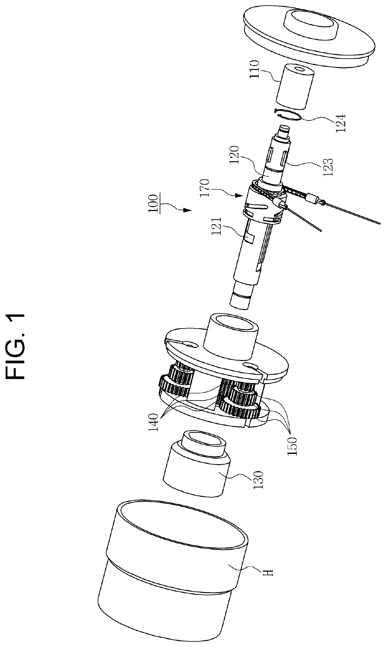
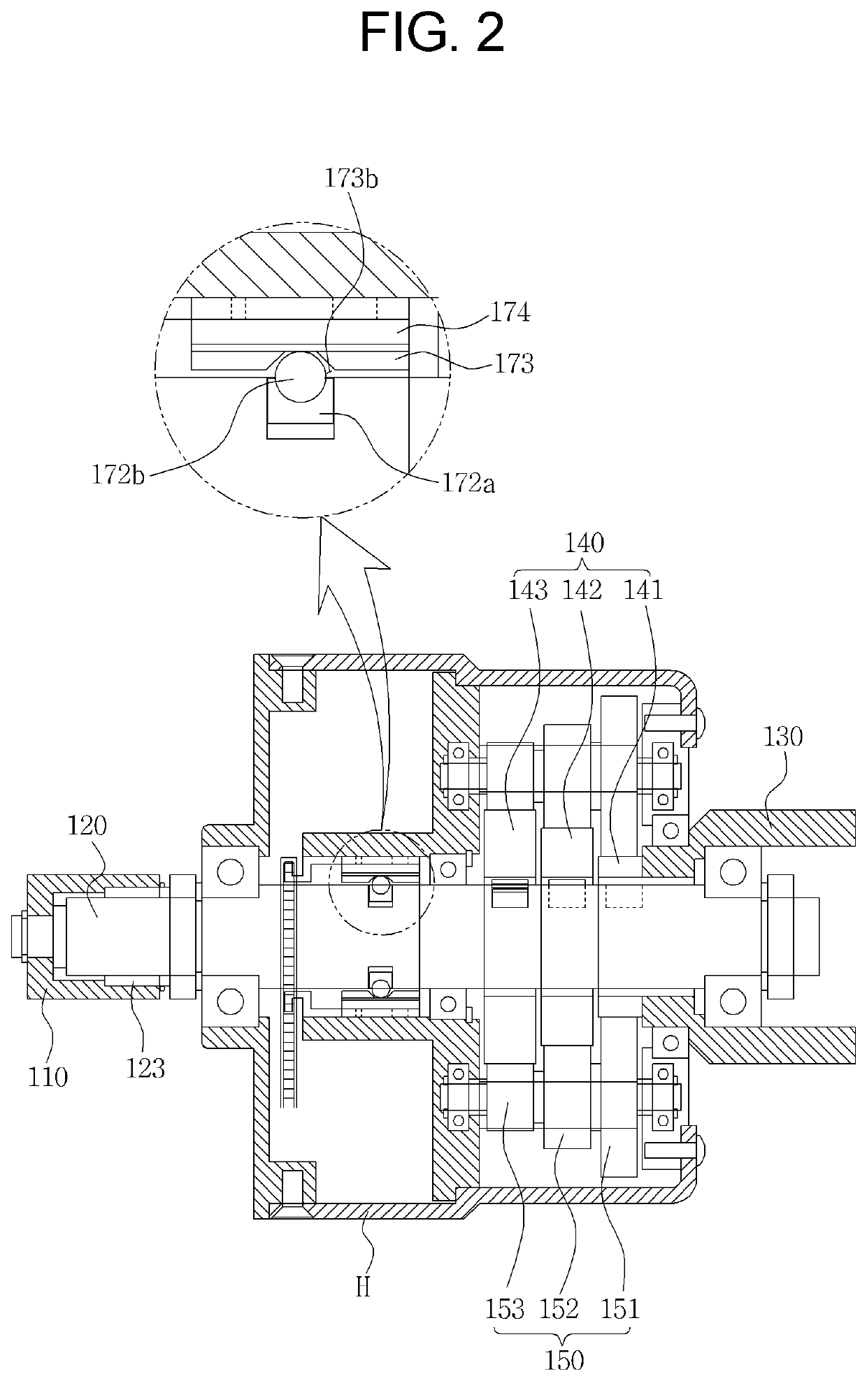
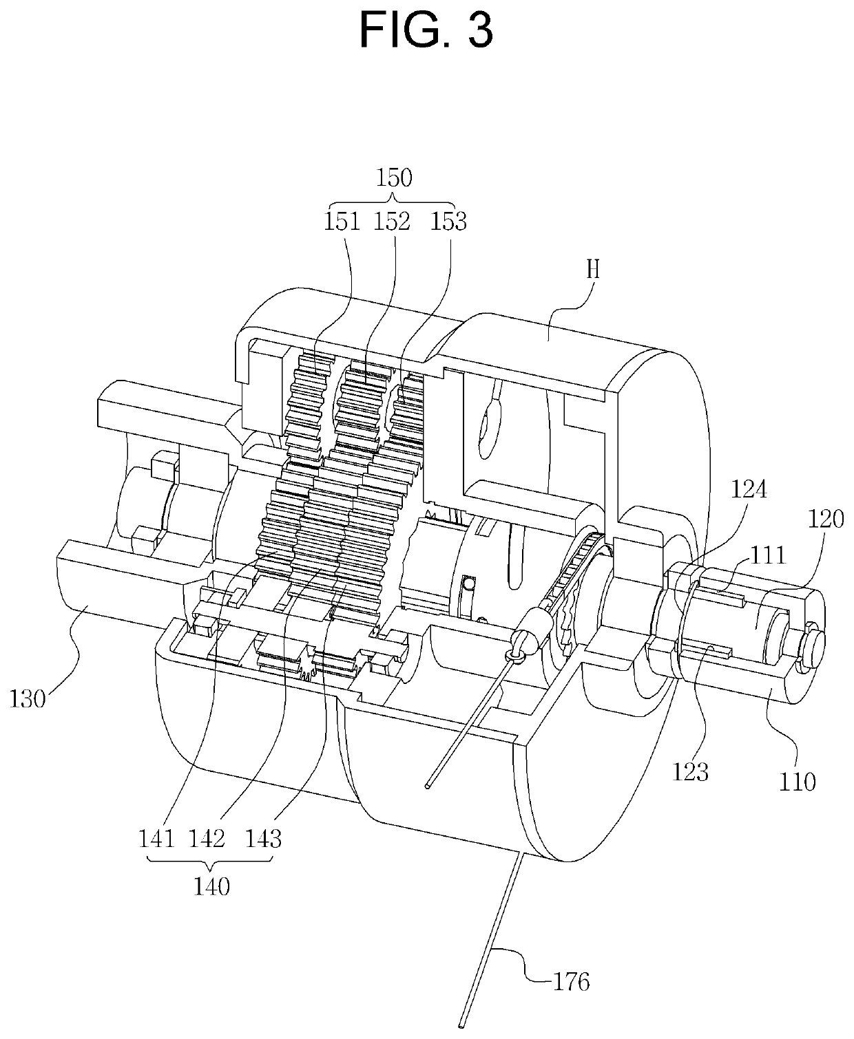
[0122]Referring to FIGS. 11 to 13, a multi-gear transmission 300 for a motor according to a third preferred embodiment of the present invention includes: housings H and H1 to H3; an input shaft 320 rotating by receiving driving force of a motor (not shown); four driving gears 340 through the centers of which the input shaft 320 is disposed; four driven gears 350 externally meshed with the driving gears 340; and an output shaft 330 which is a central shaft of the driven gears 350 and is parallel with the input shaft 320.

[0123]Moreover, in this embodiment, the driving force of the motor is not directly transmitted to the input shaft 320 but is transmitted to the input shaft 320 through a shift clutch 310.

[0124]The input shaft 320 has two seating grooves 321 (see FIG. 14) and two pawls 361a and 361b seated on the seating grooves 321. Especially, an elastic member 322 (in FIG. 14) is mounted on the seating groove 321 so that the pawl 361 is elastically supported to protrude outwardly fr...


PUM


Abstract

Provided is a transmission for a motor including: an input shaft rotating by driving force transmitted from the motor and having a plurality of pawls disposed on the outer circumferential surface; controller for controlling protrusion and retraction of the pawls; a plurality of driving gears through the centers of which the input shaft passes, which have ratchets formed on the inner circumferential surfaces thereof so as to be engaged with the pawls, and which are different in the number of gear teeth; a plurality of driven gears which are externally meshed with the driving gears and are different in the number of gear teeth; and an output unit for outputting rotary speed changed in speed by the driving gears and the driven gears.

Description

TECHNICAL FIELD[0001]The present invention relates to a multi-gear transmission having three or more speeds, for a motor and, more specifically, to a transmission for a motor, which has a simple structure without a complicated hydraulic device and the like, has no energy consumption in shifting gears and shifting shock, and can be freely designed and manufactured with a desired number of speeds in a desired transmission gear ratio.BACKGROUND ART[0002]Recently, lots of electric vehicles are coming into wide use, but a multi-gear transmission of a motor for transportation means is not yet commercialized.[0003]An engine cannot obtain torque at the time of initial startup, but a motor generates the maximum torque at the time of initial startup so as to provide excellent starting acceleration power. As described above, the motor is more suitable for transportation means in torque-speed characteristics than the engine.[0004]However, the motor is very wasteful with fuel (electricity) and i...

Claims


Application Information

Patent Timeline
Patent Type & Authority Patents(United States)
IPC IPC(8): F16H3/089F16H61/02F16H61/684
CPCF16H3/089F16H61/0297F16H61/684F16H2200/0039F16H2306/40H02K7/116F16H2200/0021F16H2200/0043F16H2063/3096F16H63/30F16H3/083F16H61/36H02K7/10H02K7/102
Inventor KIMPARK, HYUNG BAEKIM, JOON SEOSUK, EUNG SIKJEON, YOUNG SHIKKIM, YOO GYUNHWANG, JAE HOPARK, HYEONG KEUNSEO, DONG UKKIM, JUNG HUNJU, YOUNG HEE
Owner KIM E E
Why Eureka
Try Eureka