Tape cartridge

a tape cartridge and tape technology, applied in the field of tape cartridges, can solve the problems of complication of work and complication of the assembling of the tape cartridge, and achieve the effect of reducing the number of tape cartridges

Inactive Publication Date: 2017-07-06
SEIKO EPSON CORP
View PDF2 Cites 17 Cited by
  • Summary
  • Abstract
  • Description
  • Claims
  • Application Information

AI Technical Summary

Benefits of technology

[0006]An object of the present invention is to provide a tape cartridge which is capable of stabilizing the rotation of the tape roll, and smoothly performing the assembling.Solution to Problem
[0020]According to this configuration, since the rotation of the spool is restricted by the coil spring, it is possible to prevent problems such as feeding end of the print tape drawn into the cartridge casing due to vibration or the like.

Problems solved by technology

However, since the pivoting support section and the rotating guide section are provided in the lower casing, there is a problem of complication of work occurs in the assembling of the tape cartridge.
Therefore, there was a problem of complication of the assembling of the tape cartridge.

Method used


Image

  • Tape cartridge
  • Tape cartridge
  • Tape cartridge

Examples


first embodiment

[0053][First Embodiment of Tape Cartridge]

[0054]Next, the tape cartridge 1 according to the first embodiment will be described with reference to FIGS. 3 to 6B.

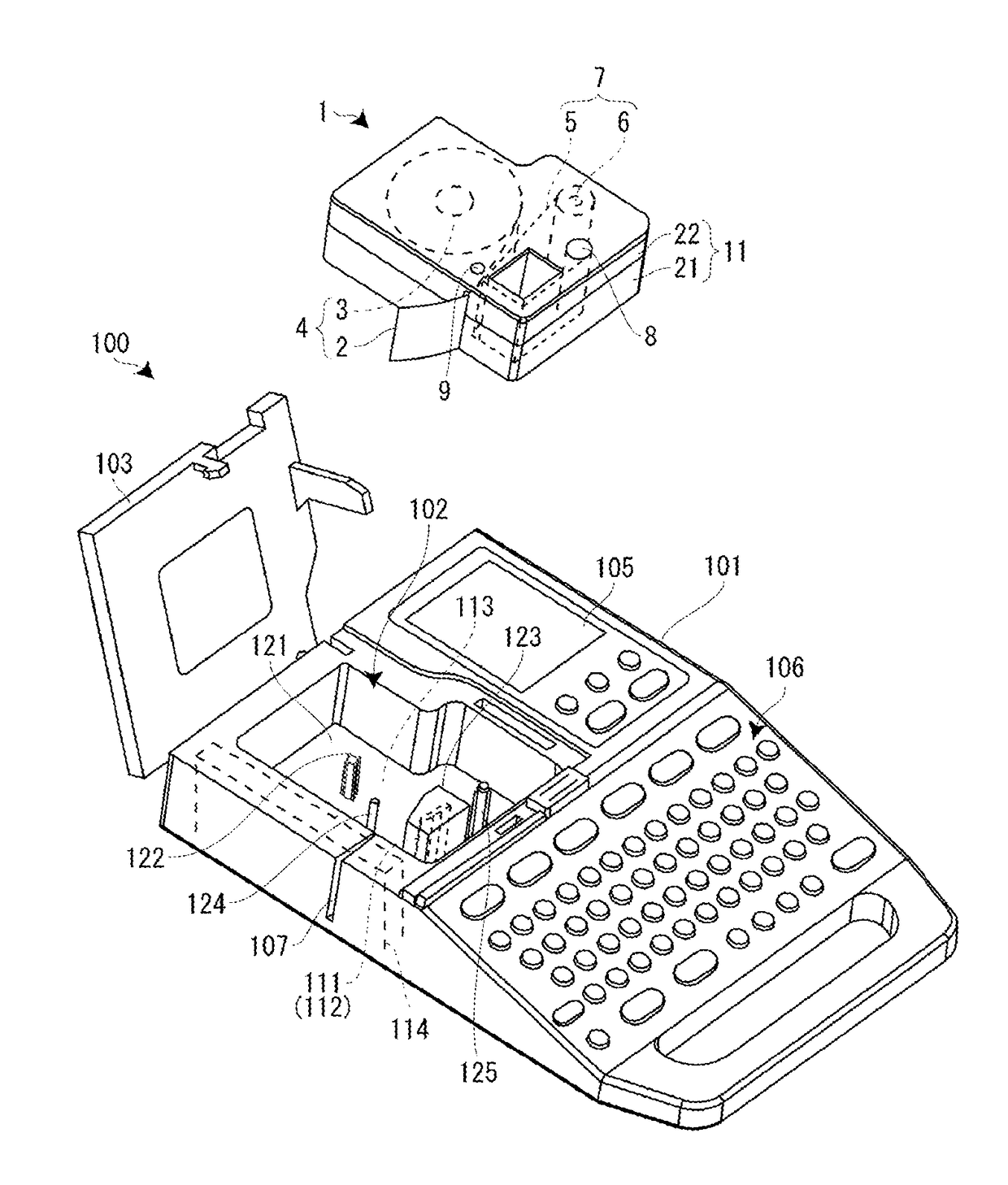
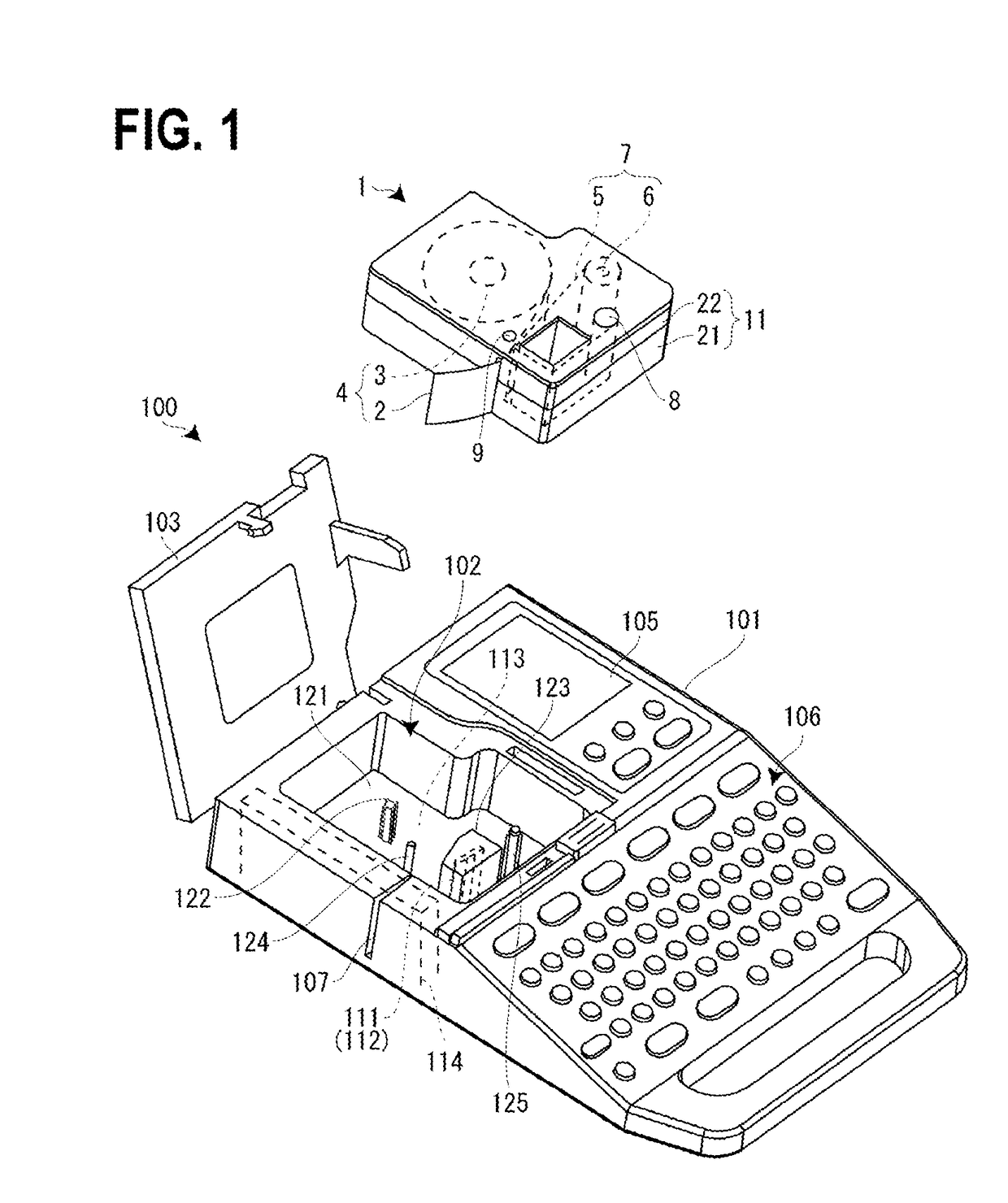
[0055]As described above, a core recess 15 is formed on the back surface of the tape cartridge 1, and the base protrusion 122 is formed in the cartridge mounting section 102, correspondingly. The base protrusion 122 is formed integrally with a cylindrical protrusion main body 131, and four protrusions 132 protruding at the four locations in the circumferential direction of the protrusion main body 131. The base protrusion 122 is integrally formed with the mounting base 121 (see FIG. 3).

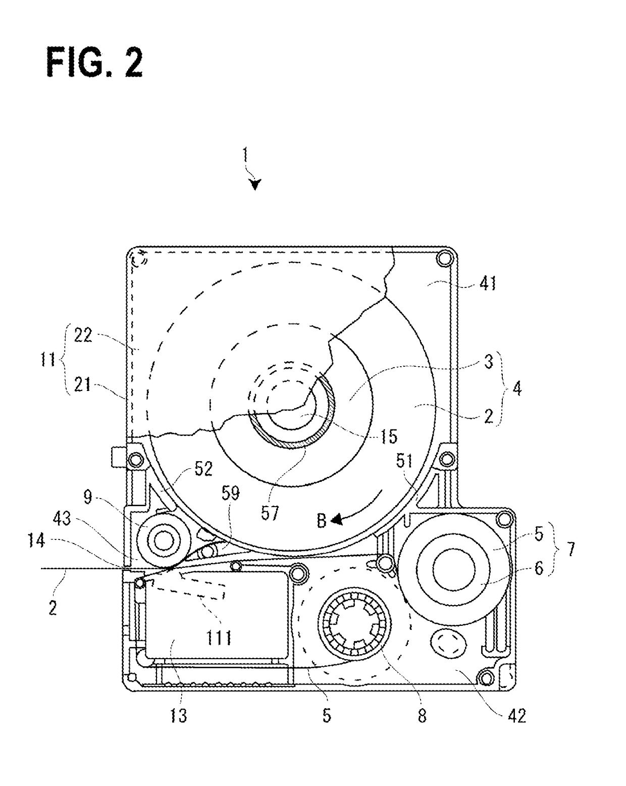
[0056]On the other hand, the core recess 15 is continuous to the cartridge casing 11 to include a fitting opening 31 formed in the bottom wall 28 of the lower casing 21. The fitting opening 31 constituting the base of the core recess 15 is fitted to the base protrusion 122 of the cartridge mounting section 102. Therefore, the fitting opening 31 ...

second embodiment

[0064][Second Embodiment of Tape Cartridge]

[0065]Next, a tape cartridge 1A according to a second embodiment will be described with reference to FIGS. 7 and 8. In the second embodiment, differences from the first embodiment will be mainly described.

[0066]In the tape cartridge 1A, the rotating guide section 57 is made up of guide piece 57A (sliding-contact piece) which extending in the radial direction. Even in this case, the guide piece 57A is formed integrally with the upper casing 22 (the top wall 24). Further, the guide piece 57A is formed in a thick plate shape, and protrudes to be short from the inner surface of the top wall 24. One of the outer end surfaces of the guide piece 57A comes into sliding contact with the upper inner circumferential surface of the tape core 61 to guide the rotation of the spool 3 (the tape roll 4).

[0067]In this second embodiment, the rotation of the tape roll 4 can be stabilized by the guide piece 57A. Further, since the guide piece 57A is provided on...

third embodiment

[0068][Third Embodiment of Tape Cartridge]

[0069]Next, a tape cartridge 1B according to a third embodiment will be described with reference to FIG. 9. In the third embodiment, differences from the first embodiment will be mainly described.

[0070]In the tape cartridge 1B, the rotating guide section 57 is made up of three arc-shaped guide pieces 57B (sliding-contact pieces). The three arc-shaped guide pieces 57B have a form in which three positions in the circumferential direction of the rotating guide section 57 of the first embodiment are removed, and the three arc-shaped guide pieces 57B are circumferentially evenly arranged. In this case, the three arc-shaped guide pieces 57B are formed integrally with the upper casing 22 (the top wall 24). Each arc-shaped guide piece 57B is formed in an arc shape, and protrudes to be short from the inner surface of the top wall 24. The three arc-shaped guide pieces 57B come into sliding contact with the upper inner circumferential surface of the ta...


PUM


Abstract

A tape cartridge detachably mounted to a cartridge mounting section of a tape printer includes a cartridge casing that has a first casing on a front side in a mounting direction in which the tape cartridge is mounted to the cartridge mounting section, and a second casing on a rear side with respect to the front side in the mounting direction, a tape roll that is accommodated in the cartridge casing and in which a print tape is wound around a spool, and a rotating guide section that is provided in the second casing and guides the rotation of the tape roll in sliding contact with an inner circumferential surface of the spool.

Description

CROSS-REFERENCE TO RELATED APPLICATIONS[0001]This application is the U.S. National Phase under 35 U.S.C. §371 of International Application No. PCT / JP2015 / 071888 filed on Jul. 31, 2015, which in turn claims the benefit of Japanese Application No. 2014-200444 filed on Sep. 30, 2014, the disclosures of which are expressly incorporated by reference herein.TECHNICAL FIELD[0002]The present invention relates to a tape cartridge of two division structures in which a tape roll formed by winding a print tape around a spool is accommodated.BACKGROUND ART[0003]In the related art, as this kind of the tape cartridge, (see JP-2012-006295), a tape cartridge which stores a tape body formed by winding a print tape around a spool has been known. An outer shell of the tape cartridge is formed by a cartridge casing including an upper casing and a lower casing. The cartridge casing stores a tape body in which the print tape is wound around the spool, a ribbon body in which an ink ribbon is wound around a...

Claims


Application Information

Patent Timeline
Patent Type & Authority Applications(United States)
IPC IPC(8): B41J32/00B41J3/407
CPCB41J3/4075B41J32/00B41J15/044B41J17/32B41J3/36B41J15/04
Inventor KOSUGE, SHINSAKUNAKAJIMA, YASUMASA
Owner SEIKO EPSON CORP
Why Eureka
Try Eureka