
Atomizing device and electronic cigarette having same

a technology of electronic cigarettes and atomizers, which is applied in the field of electronic cigarettes, can solve the problems of harmful health effects and high temperature of heating components, and achieve the effects of avoiding overheating the electronic cigarette shell, preserving the taste of smoke, and saving energy

Active Publication Date: 2017-07-13
JOYETECH CHANGZHOU ELECTRONICS
View PDF2 Cites 59 Cited by
  • Summary
  • Abstract
  • Description
  • Claims
  • Application Information

AI Technical Summary

Benefits of technology

The patent describes an electronic cigarette with a device that can control the temperature of the heating part, which is important for maintaining the taste of the smoak and preventing harmful substances from being released during smoking. This device can also avoid overheating the shell of the electronic cigarette and reduce the risk of injury to the user. The temperature control is achieved through a simple push-to-control switch, which is connected to a control device and is independent of the heating member. This allows for individual temperature control and adjustment based on the user's needs. The device also includes a regulating circuit to adjust the temperature, preventing the temperature from cooling down too rapidly. The heating member temperature can be calculated based on pre-stored data and the user can enter the desired target temperature through an input unit. The heating member can directly transmit the temperature change to the control device, simplifying the structure and operation process.

Problems solved by technology

However, with increasing of an output power of a cell assembly of the electronic cigarette and decreasing of a resistance of a heating member of a atomizing device for the electronic cigarette, a temperature of the heating member can become too high.
An excessively high temperature of the heating member may lead the smoke liquid, the wax or the tobacco producing and releasing some substances, which are harmful to health.

Method used


Image

  • Atomizing device and electronic cigarette having same
  • Atomizing device and electronic cigarette having same
  • Atomizing device and electronic cigarette having same

Examples


first embodiment

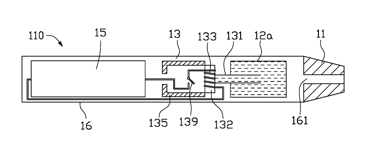
[0070]FIG. 1 illustrates an electronic cigarette 110. The electronic cigarette 110 can include a suction nozzle 11, a liquid reservoir 12a, an atomizing device 13, a power supply device 15, and a shell 16. An end of the suction nozzle 11 can be coupled to the shell 16. All of the liquid reservoir 12a, the atomizing device 13, and the power supply device 15 can be positioned in the shell 16. The atomizing device 13 can be electrically coupled to the power supply device 15. An end of the shell 16 that is adjacent to the suction nozzle 11 can define a vent hole 161. The vent hole 161 can be in fluid communication with the suction nozzle 11. Smoke liquid received in the liquid reservoir 12a can be carried to the atomizing device 13. After the atomizing device 13 is driven by the power supply device 15, the smoke liquid can be heated and atomized, thus the user can enjoy a smoking experience.

[0071]The atomizing device 13 can include a first liquid guiding member 131, a second liquid guid...

second embodiment

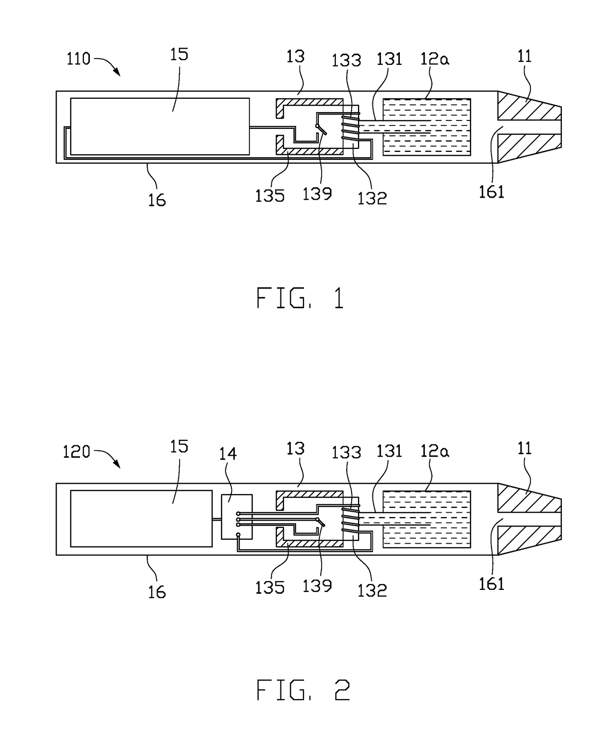
[0076]FIG. 2 illustrates an electronic cigarette 120. A difference between the electronic cigarette 120 of the second embodiment and the electronic cigarette 110 of the first embodiment is as follows. The heating member 133 and the temperature control switch 139 are not directly and electrically coupled to each other in series, but each one is coupled independently to a control device 14. The control device 14 is electrically coupled to the power supply device 15. The temperature control switch 139 can have one of the following characteristics, wherein each characteristics may signify a plurality of properties: the first is that the temperature control switch 139 can be switched on when the temperature ts of the temperature control switch 139 is less than the operating temperature TM, and can be switched off when greater; the second is the opposite of the above, namely, the temperature control switch 139 can be switched off when the temperature ts of the temperature control switch 1...

third embodiment

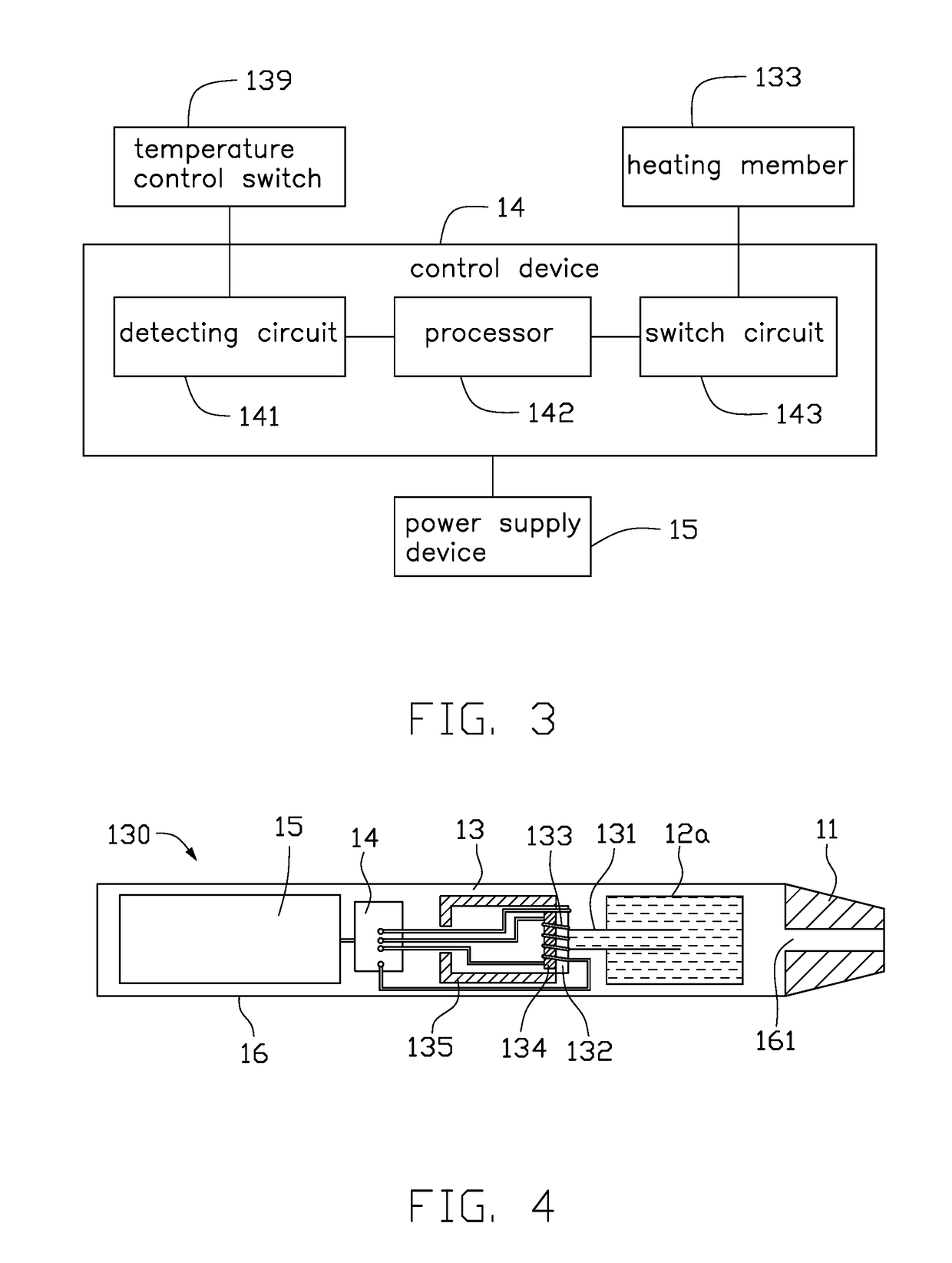
[0084]FIGS. 4-5 illustrate an electronic cigarette 130. The difference between the electronic cigarette 130 of the third embodiment and the electronic cigarette 120 of the second embodiment is as follows. A temperature sensor 134 replacing the temperature control switch 139 can be electrically coupled to the control device 14.

[0085]The second liquid guiding member 132 can be positioned adjacent to or clinged to the temperature sensor 134. The heating member 133 may be sleeved on, twined around, adhered to or clinged to both of the second liquid guiding member 132 and the temperature sensor 134 or it may be that the heating member 133 is sleeved on, twined around, adhered to or clinged to the second liquid guiding member 132 only. In an alternative embodiment, the second liquid guiding member 132 can be positioned adjacent to or clinged to the temperature sensor 134, either the second liquid guiding member 132 and the temperature sensor 134 are cooperatively sleeved on, twined around...


PUM


Abstract

An atomizing device is provided. The atomizing device includes a heating member and a temperature control switch. The temperature control switch is positioned adjacent to the heating member or the heating member is sleeved on the temperature control switch. Both of the heating member and the temperature control switch are electrically coupled to a power supply device. An electronic cigarette including the atomizing device is also provided.

Description

CROSS-REFERENCE TO RELATED APPLICATIONS[0001]This application is a continuation in part of International Patent Application NO. PCT / CN2015 / 087602, filed on Aug. 20, 2015, and of International Patent Application NO. PCT / CN2015 / 087603, filed on Aug. 20, 2015, both of which claim priority to Chinese Patent Application No. CN201410765761.6, filed on Dec. 12, 2014. The contents of all of these specifications are incorporated herein by reference.FIELD[0002]The subject matter herein generally relates to an electronic cigarette, and particularly to an atomizing device that can sense the temperature change of a heating member and an electronic cigarette including the atomizing device having a temperature control function.BACKGROUND[0003]An electronic cigarette, also known as a virtual cigarette, is used for replacing a normal cigarette. The electronic cigarette has a similar taste as a cigarette. However, with increasing of an output power of a cell assembly of the electronic cigarette and d...

Claims


Application Information

Patent Timeline
Patent Type & Authority Applications(United States)
IPC IPC(8): A24F47/00H05B1/02A24F40/10A24F40/20A24F40/44A24F40/46A24F40/485A24F40/50
CPCA24F47/008H05B2203/021H05B1/0244H05B3/16H05B2203/014A24F40/46A24F40/10A24F40/44A24F40/50A24F40/20A24F40/485
Inventor QIU, WEI-HUA
Owner JOYETECH CHANGZHOU ELECTRONICS
Learn More