Shoe Heel Counter

a technology of shoe heel counter and heel, which is applied in the direction of uppers, bootlegs, stiffners, etc., can solve the problems of chafing and/or blistering, no comfort for the heel region of the wearer, and discomfort for the wearer

Inactive Publication Date: 2017-07-13
FERGUSON BEVERLY
View PDF29 Cites 11 Cited by
  • Summary
  • Abstract
  • Description
  • Claims
  • Application Information

AI Technical Summary

Benefits of technology

[0013]In view of the above problems, it is an object of the present invention to provide a counter with cut-out region

Problems solved by technology

A loose-fitting shoe, such as a high-heeled shoe of the strapless type, will cause discomfort to a wearer.
This is partially due to unwanted movement of the heel of the wearer's foot within the shoe.
This movement causes rubbing of the heel portion of the foot against the inside upper portion of the shoe, which leads to chafing and/or blistering.
A drawback of the shoe described above and depicted in FIG. 1, using the conventional counter 102 as shown in FIGS. 1 and 2, is that there is no comfort provided to the region of the wearer's heel.
As a result, rubbing or chafing will occur which, oftentimes, results in the wearer attaching one or more padded bandages to the sore area of the foot.
However, such grips require the wearer to apply them and

Method used


Image

  • Shoe Heel Counter
  • Shoe Heel Counter
  • Shoe Heel Counter

Examples


Embodiment Construction

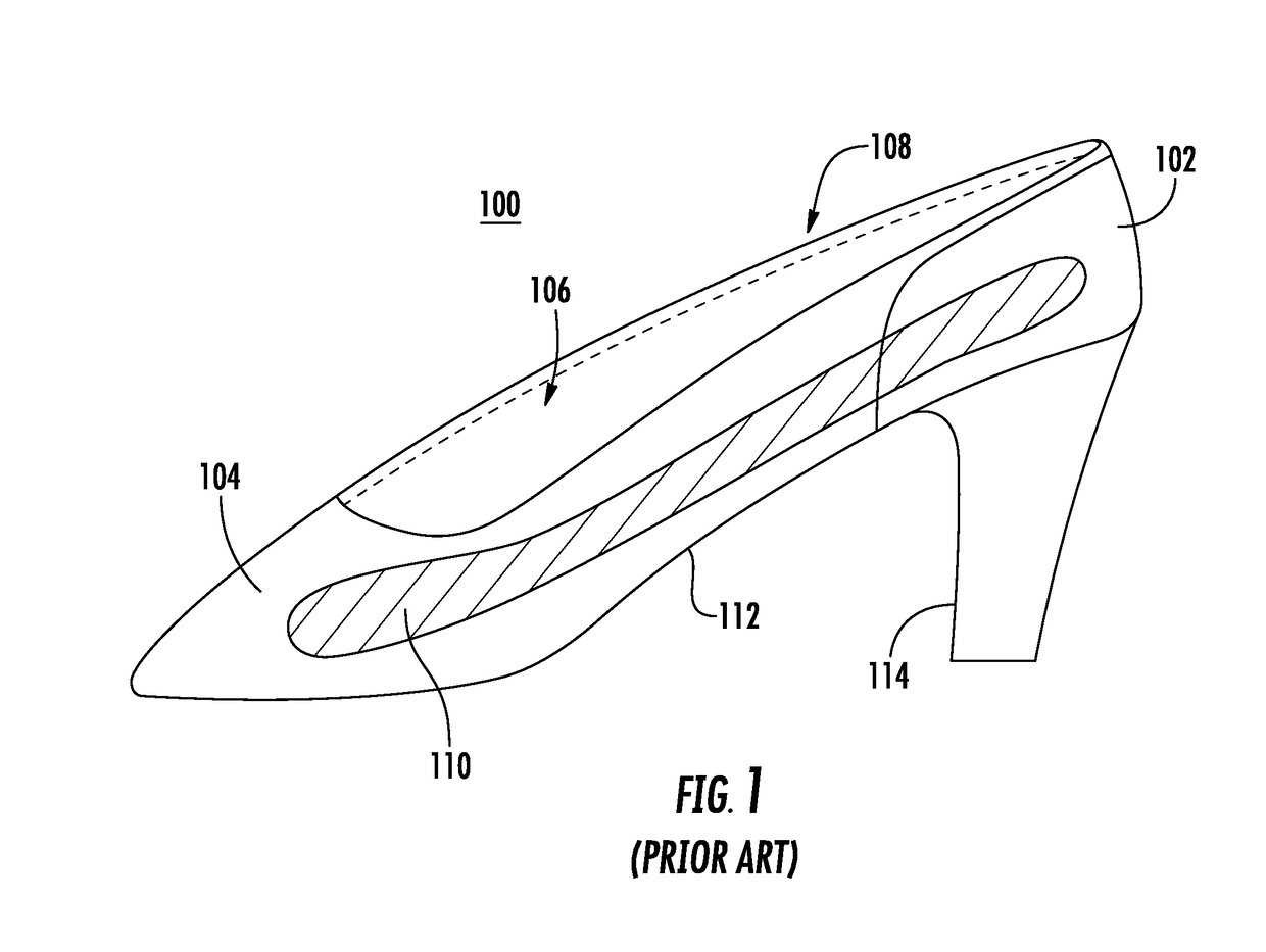
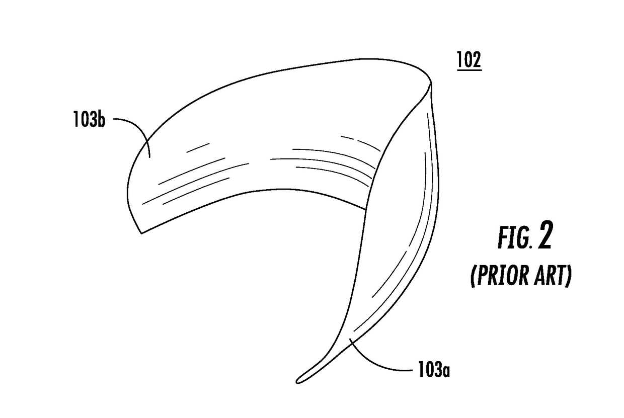
[0036]Reference numerals of components that are unchanged from those shown in FIGS. 1 and 2 will be maintained in the drawings showing the improved shoe with the modified counter.

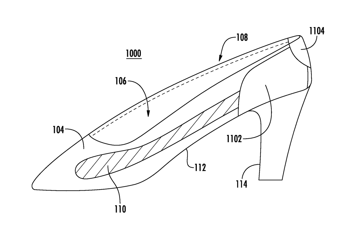
[0037]An improved shoe 1000, as shown in FIGS. 3-7, alleviates the potential discomfort that comes from the use of a conventional shoe counter that extends in a region about a shoe upper proximate a wearer's heel. The improved shoe 1000 incorporates a heel pillow 1104 in a location opposite the region of the wearer's heel that would otherwise undergo chafing, but does so using a modified counter 1102 with a cutout region 1106 that prevents the heel pillow 1104 from causing an uncomfortable projection into the shoe at the heel.

[0038]Thus, as shown in FIGS. 3-7, and in accordance with the present invention, a modified counter 1102 is proposed as shown in FIGS. 3-7. The modified counter 1102 is positioned between the lining 106 and upper 104 and is formed, as can be seen in FIG. 4, with a scoop or cut-out regi...


PUM

PropertyMeasurementUnit
Thermoplasticityaaaaaaaaaa

Abstract

A counter for a shoe having an upper, a lining configured to be connected with the upper along a top edge of the shoe, a cushioning heel pillow arranged in a position opposite the heel of a wearer's foot, and an insole forming a foot bed of the shoe. The counter includes a member having an upper edge having a cut-out region forming a valley, a lower edge forming an anchor region, and first and second side wings. The counter is configured to be positioned between the lining and the upper at a heel portion of the shoe such that, in an assembled shoe, the first and second side wings wrap around the heel of the shoe and the valley accommodates an extension of the heel pillow therethrough.

Description

CROSS-REFERENCE TO RELATED APPLICATION[0001]This application claims benefit under 35 U.S.C. 119(e) to U.S. Provisional Patent application No. 62 / 277,247, filed Jan. 11, 2016, the entire contents of which are incorporated by reference herein.BACKGROUND OF THE INVENTION[0002]Field of the Invention[0003]The present invention is directed to an improvement for women's shoes and, particularly, shoes of the high-heeled type that do not have a heel strap.[0004]Discussion of Related Art[0005]A loose-fitting shoe, such as a high-heeled shoe of the strapless type, will cause discomfort to a wearer. This is partially due to unwanted movement of the heel of the wearer's foot within the shoe. This movement causes rubbing of the heel portion of the foot against the inside upper portion of the shoe, which leads to chafing and / or blistering. In addition, known shoes include a counter member, which is also located between the upper and the lining and which extends at the back of the shoe across both ...

Claims


Application Information

Patent Timeline
IPC IPC(8): A43B23/17A43B23/14A43B23/02A43B23/07
CPCA43B23/14A43B23/07A43B23/17A43B23/028A43B23/16
Inventor FERGUSON, BEVERLY
Owner FERGUSON BEVERLY
Why Eureka
Try Eureka