Operation control system and operation control method

a technology of operation control and control system, applied in the direction of programmed control, manipulators, instruments, etc., can solve the problems of mechanical stopper deformation and actuator damage, and achieve the effect of avoiding the damage of the actuator

Active Publication Date: 2017-07-13
HONDA MOTOR CO LTD
View PDF2 Cites 2 Cited by
  • Summary
  • Abstract
  • Description
  • Claims
  • Application Information

AI Technical Summary

Benefits of technology

[0011]According to the operation control system configured as above by considering the above fact, in a case where the position and the velocity of the first mechanical element depart from the predetermined allowable range, a stop instruction for stopping the operation of the actuator is outputted. As a result, the operation of the actuator is stopped and the movable member is deaccelerated. Thus, the first mechanical element is prevented from making contact with the second mechanical element. Alternatively, even when the first mechanical element makes contact with the second mechanical element, a force generated against the first mechanical element (or the second mechanical element) at a time of contact between the first mechanical element and the second mechanical element is prevented from being excessively large. In this way, while deformation of the first mechanical element and the second mechanical element is prevented or reduced, the movable range of the movable member can be utilized to the maximum.
[0016]Here, as the position of the first mechanical element is closer to the contact position relative to the second mechanical element, the absolute value of the value of the function becomes smaller. Accordingly, the absolute value of the velocity of the first mechanical element at a timing for the actuator control unit to stop the operation of the actuator is expected to be smaller as the position of the first mechanical element is closer to the contact position. As a result of this, a force generated against the first mechanical element (or the second mechanical element) when the first mechanical element makes contact with the second mechanical element is prevented from being excessively large.
[0021]Since the torque applied to the first mechanical element (or the second mechanical element) accordingly falls within the allowable range, the movable range of the movable member can be utilized to the maximum while deformation of the first mechanical element or the second mechanical element is prevented or reduced.
[0023]According to the operation control system configured as above, the torque τlim generated against the first mechanical element and the second mechanical element at a time of contact between the first mechanical element and the second mechanical element is smaller than both the shearing load of the first mechanical element and the shearing load of the second mechanical element. As a result, damage to the first mechanical element or the second mechanical element due to the torque τlim is prevented.

Problems solved by technology

Meanwhile, without a limit provided by the software limit, contact between the mechanical stopper of the arm and the mechanical stopper of the robot joint part may occur to cause not only deformation of any of the mechanical stoppers but also damage to the actuator.

Method used


Image

  • Operation control system and operation control method
  • Operation control system and operation control method
  • Operation control system and operation control method

Examples


Embodiment Construction

[0032]An embodiment of the present invention is described with reference to FIGS. 1 to 5.

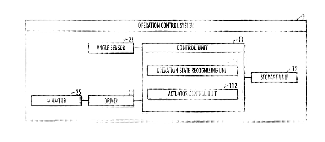
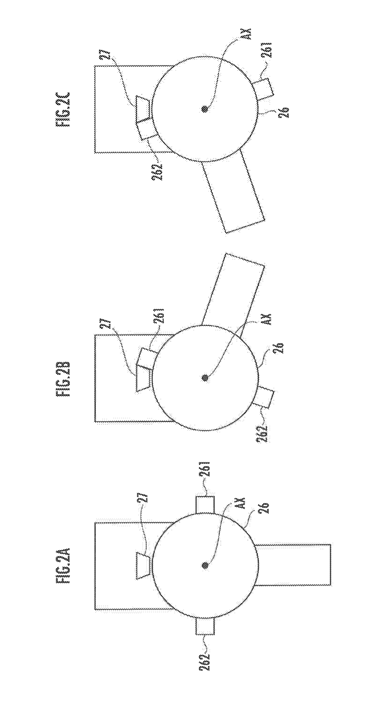
[0033]An operation control system 1, which is mounted on, for example, a robot (not illustrated), outputs an instruction to an actuator 25 provided in the robot thereby moving an arm 26 (see FIG. 2), as a movable member, of the robot. The operation control system 1 does not need to be actually mounted on the robot. For example, the operation control system 1 may output an instruction to the actuator 25 through wireless or wired communication.

[0034]The operation control system 1 of the present invention is applicable to, in addition to robots, machines including industrial machines in which movable members such as arms thereof are moved by actuators and the movable ranges of the movable members are limited by mechanical elements such as mechanical stoppers.

[0035]As illustrated in FIG. 1, the operation control system 1 includes a control unit 11, a storage unit 12, an angle sensor 21, a driver 24,...


PUM


Abstract

Provided are an operation control system and an operation control method for a movable member, which allow the movable range of the movable member to be utilized to the maximum while deformation of a mechanical element is prevented or reduced. An operation control system 1 includes: a movable member 26 having first mechanical elements 261, 262; an actuator 25 which moves the movable member 26 at a variable velocity; and a second mechanical element 27 which is fixed at a position so as to be capable of making contact with the first mechanical elements 261, 262. When the position and the velocity of the first mechanical element 261 or 262 depart from a predetermined allowable range in a two-dimensional coordinate system expressed by a position and a velocity, a stop instruction is outputted to the actuator 25.

Description

BACKGROUND OF THE INVENTION[0001]Field of the Invention[0002]The present invention relates to a system and a method of controlling an operation of a movable member the movable range of which is limited by a mechanical element.[0003]Description of the Related Art[0004]Techniques in industrial robots are conventionally known in which mechanical stoppers (mechanical elements) placed at ends of operation ranges of arms (movable members) on each of the joint parts are used for limiting the operation ranges (for example, see Japanese Patent Laid-Open No. S63-77692).[0005]Japanese Patent Laid-Open No. S63-77692 proposes a control device in which while the arrangement position of a mechanical stopper placed on a robot joint part is variable, a rotational angle between a predetermined position in the operational range of an arm and the arrangement position of the mechanical stopper is measured, positional data of a software limit is calculated on the basis of the measurement value obtained b...

Claims


Application Information

Patent Timeline
Patent Type & Authority Applications(United States)
IPC IPC(8): B25J9/16
CPCB25J9/1633B25J9/1666B25J9/1676G05B2219/40552
Inventor OSADA, MASAHIKOKANEMOTO, YOSHIKI
Owner HONDA MOTOR CO LTD
Why Eureka
Try Eureka