
Impact damping device for print-head assembly and printing apparatus incorporating same

a technology of impact damping device and printhead assembly, which is applied in the direction of power drive mechanism, printing, spacing mechanism, etc., can solve the problems of inability to meet the requirements of length, large carriage length, and inconvenient installation of length, so as to reduce the required installation space, reduce manufacturing costs, and reduce the effect of overrun spa

Active Publication Date: 2017-07-13
OCE HLDG BV
View PDF7 Cites 1 Cited by
  • Summary
  • Abstract
  • Description
  • Claims
  • Application Information

AI Technical Summary

Benefits of technology

The present invention provides a new and improved print-head assembly for a printing apparatus with several technical effects. Firstly, the assembly has a new design that requires less overrun space, which enables a more efficient printing process. Secondly, the assembly includes a retractable impact member that can absorb or damp impact from operators or foreign objects on the printing surface. Thirdly, the assembly includes one or more sensors and a control unit for detecting and responding to impact at the contact surface of the impact member, which can prevent or avoid the risk of personal injury or damage to the printing apparatus. Overall, the invention saves on installation space, reduces manufacturing costs, and improves printing efficiency.

Problems solved by technology

The conventional safety fence design, however, consumes space to provide for a travel length for the carriage to stop, which length is inevitably required in view of inertia of the carriage, for example.
This design results in a considerable carriage length, which requires or demands for additional overrun space on opposite sides of the printing surface.

Method used


Image

  • Impact damping device for print-head assembly and printing apparatus incorporating same
  • Impact damping device for print-head assembly and printing apparatus incorporating same
  • Impact damping device for print-head assembly and printing apparatus incorporating same

Examples


Embodiment Construction

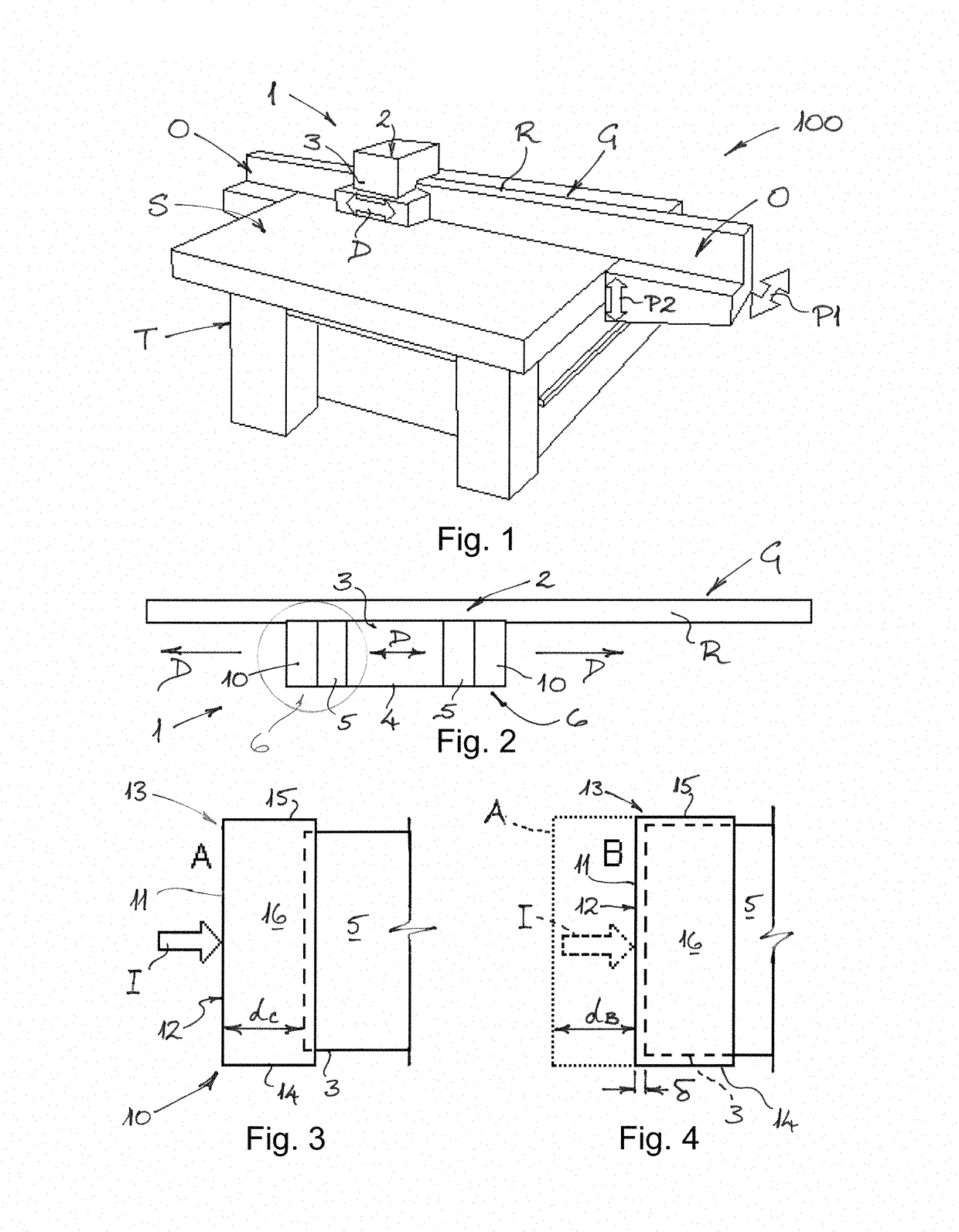
[0033]With reference firstly to FIG. 1 and FIG. 2 of the drawings, a printing apparatus 100 is shown comprising a table T having a flat upper printing surface S upon which the print medium (not shown) is supported during the printing process. Extending over or across the printing surface S is a gantry G which provides a track or rail R upon which a print-head assembly 1 is movably supported. In this way, the print-head assembly 1 is able to move back and forth in travel directions D along the track or rail R of the gantry G across the printing surface S. In a typical printing apparatus 100, the print-head assembly 1 may have a mass of about 100 kg and the width of the printing area may be 3 or 4 metres. The gantry provides an over-run area O on both ends of the track or rail R so that the print-head assembly 1 is able to use a maximum of the printing surface S available. As is apparent from the double-headed arrows P1, P2 in FIG. 1, positional adjustment of the gantry G with respect...


PUM


Abstract

A print-head assembly for a printing apparatus includes: a carriage with a frame configured to be supported on a gantry for movement in a travel direction over a print surface; a print-head unit having one or more print heads mounted on the carriage; and an impact damping device mounted on an end region of the carriage in the travel direction, wherein an impact member of the damping device presents a contact surface in the travel direction. The impact member is mounted to the carriage frame for resilient movement over a buffer distance substantially parallel to the travel direction between a first extended position and a second retracted position for absorbing or damping an impact during movement of the carriage in the travel direction.

Description

FIELD OF THE INVENTION[0001]The present invention relates to a printing apparatus, and more specifically to an impact damping device for a print-head assembly in a printing apparatus.BACKGROUND OF THE INVENTION[0002]A print-head assembly in a printing apparatus typically includes a carriage which is supported for movement over a printing surface. The carriage incorporates or supports a print-head unit having one or more print heads which travel over the printing surface with the carriage in a travel direction. In addition to the print-head unit, the carriage may optionally support one or more curing units for curing the ink deposited by the print heads.[0003]To protect the print-head assembly from inadvertent contact by an operator or a foreign object on the printing surface which may block movement of the carriage, the conventional print-head assembly includes a safety fence or barrier. If or when an operator or a foreign object contacts the safety fence or barrier, thereby impedin...

Claims


Application Information

Patent Timeline
Patent Type & Authority Applications(United States)
IPC IPC(8): B41J25/304F16F7/00
CPCF16F7/00B41J25/304B41J19/00B41J29/08B41J29/12
Inventor OTTER, BRIAN D.ELFERINK, MAARTEN J.H.WAN, HADYLEE H.
Owner OCE HLDG BV
Learn More