Foldable propeller blade with locking mechanism

a propeller blade and locking mechanism technology, applied in the field of unmanned aerial vehicles, can solve the problems of current compact configurations that are and payload capacity, and achieve the effects of reducing space, increasing payload capacity, and limited in flight range, endurance and payload capacity

Active Publication Date: 2017-07-13
ANDURIL IND INC
View PDF36 Cites 20 Cited by
  • Summary
  • Abstract
  • Description
  • Claims
  • Application Information

AI Technical Summary

Benefits of technology

[0007]Unmanned aerial vehicles may be used for a plurality of applications. Such applications comprise commercial applications including surveillance and filming, and for military applications, reconnaissance and tactical missions. In certain circumstances, compact configurations can be beneficial to enabling particular types of missions. For example, compact configurations reduce space and enable various deployment options. However, current compact configurations are limited in flight range, endurance, and payload capacity.
[0008]Embodiments of the present disclosure provide an improved aerial vehicle with deployable components. This brief overview is provided to introduce a selection of concepts in a simplified form that are further described below in the Detailed Description. This brief overview is not intended to identify key features or essential features of the claimed subject matter. Nor is this brief overview intended to be used to limit the claimed subject matter's scope.
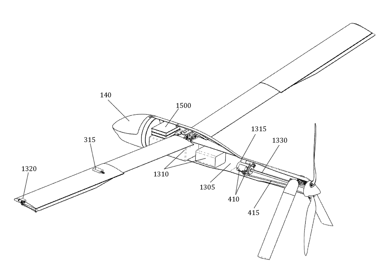
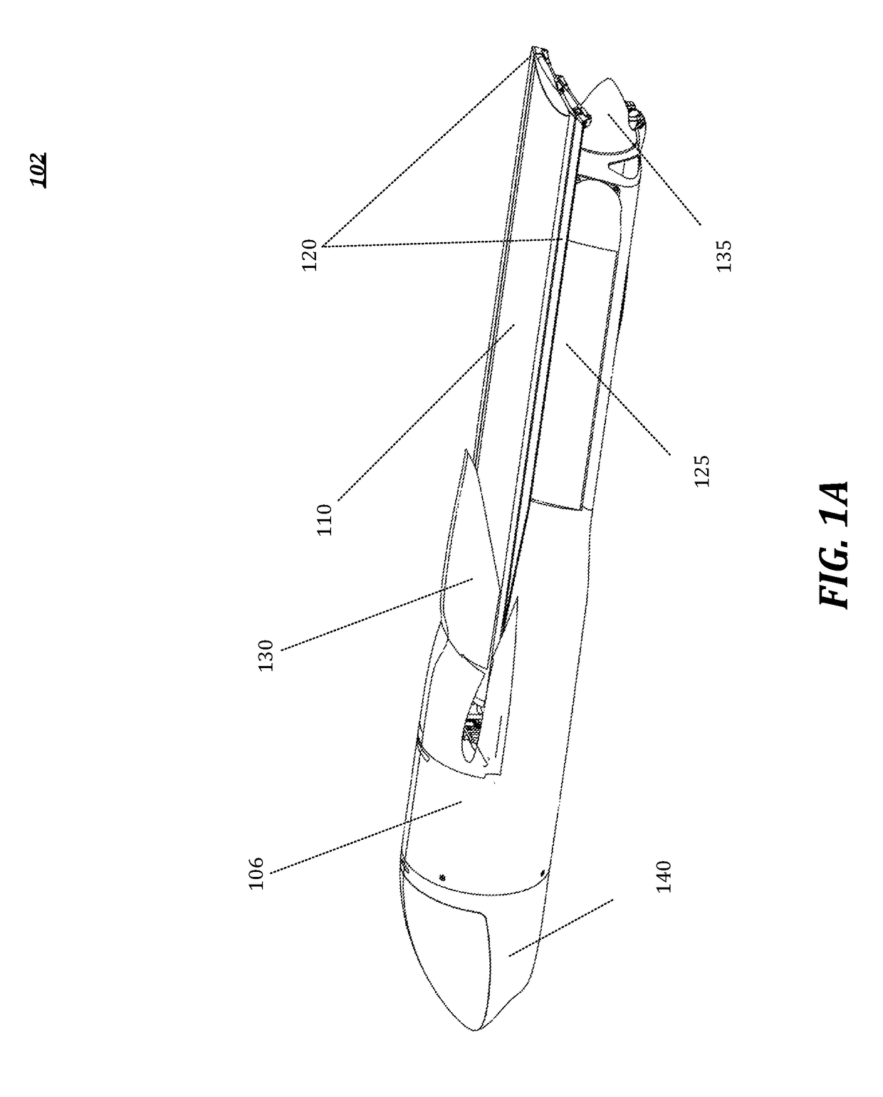
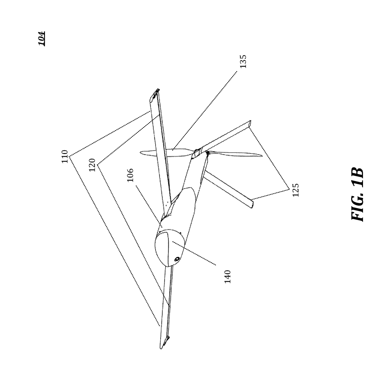
[0009]An unmanned aerial vehicle with deployable components (UAVDC) is disclosed. The UAVDC may comprise a fuselage, at least one wing, and at least one stabilizer. In some embodiments, the UAVDC may further comprise a propulsion means and / or a modular payload. The UAVDC may be configured in a plurality of arrangements. For example, in a compact arrangement, the UAVDC may comprise the at least one wing stowed against the fuselage and the at least one stabilizer stowed against the fuselage. In a deployed arrangement, the UAVDC may comprise the at least one wing deployed from the fuselage and the least one stabilizer deployed from the fuselage. In an expanded arrangement, the UAVDC may comprise the at least one wing telescoped to increase a wingspan of the deployed arrangement.

Problems solved by technology

However, current compact configurations are limited in flight range, endurance, and payload capacity.

Method used


Image

  • Foldable propeller blade with locking mechanism
  • Foldable propeller blade with locking mechanism
  • Foldable propeller blade with locking mechanism

Examples


Embodiment Construction

[0067]As a preliminary matter, it will readily be understood by one having ordinary skill in the relevant art that the present disclosure has broad utility and application. As should be understood, any embodiment may incorporate only one or a plurality of the above-disclosed aspects of the disclosure and may further incorporate only one or a plurality of the above-disclosed features. Furthermore, any embodiment discussed and identified as being “preferred” is considered to be part of a best mode contemplated for carrying out the embodiments of the present disclosure. Other embodiments also may be discussed for additional illustrative purposes in providing a full and enabling disclosure. Moreover, many embodiments, such as adaptations, variations, modifications, and equivalent arrangements, will be implicitly disclosed by the embodiments described herein and fall within the scope of the present disclosure.

[0068]Accordingly, while embodiments are described herein in detail in relation...


PUM


Abstract

An unmanned aerial vehicle with deployable components (UAVDC) is disclosed. The UAVDC may comprise a fuselage, at least one wing, and at least one control surface. In some embodiments, the UAVDC may further comprise a propulsion means and/or a modular payload. The UAVDC may be configured in a plurality of arrangements. For example, in a compact arrangement, the UAVDC may comprise the at least one wing stowed against the fuselage and the at least one control surface stowed against the fuselage. In a deployed arrangement, the UAVDC may comprise the at least one wing deployed from the fuselage and the least one control surface deployed from the fuselage. In an expanded arrangement, the UAVDC may comprise the at least one wing telescoped to increase a wingspan of the deployed arrangement. The UAVDC may also comprise a foldable propeller blade with a locking mechanism. Foldable propeller blades may have a stowed configuration and a deployed configuration, and the foldable propeller blades may pivot about a hinge to move between configurations. A foldable propeller blade in a deployed configuration may experience forward folding motion due to forces acting upon it. A locking mechanism—for example, a ratchet and pawl—may lock a foldable propeller blade into a configuration. In a locked arrangement, a UAVDC may comprise at least one foldable propeller that locks into place to prevent forward folding tendency.

Description

RELATED APPLICATIONS[0001]The present application is a continuation-in-part of:[0002]U.S. patent application Ser. No. 15 / 388,396, filed on Dec. 22, 2016, in the name of Area-I Inc. and entitled “AERIAL VEHICLE WITH DEPLOYABLE COMPONENTS,” having Attorney Docket No. 295EP.001USC1;[0003]U.S. patent application Ser. No. 15 / 388,433, filed on Dec. 22, 2016, in the name of Area-I Inc. and entitled “AERIAL VEHICLE WITH DEPLOYABLE COMPONENTS,” having Attorney Docket No. 295EP.001USC2, is hereby incorporated by reference; and[0004]U.S. patent application Ser. No. 15 / 388,478, filed on Dec. 22, 2016, in the name of Area-I Inc. and entitled “AERIAL VEHICLE WITH DEPLOYABLE COMPONENTS,” having Attorney Docket No. 295EP.001USC3, is hereby incorporated by reference.[0005]The above referenced applications claim the benefit of U.S. Provisional Application No. 62 / 254,098 filed Nov. 11, 2015, which, in turn, serves as the priority date for the present application. It is intended that each of the refere...

Claims


Application Information

Patent Timeline
Patent Type & Authority Applications(United States)
IPC IPC(8): B64C11/28B64C39/02
CPCB64C11/28B64C39/024B64C2201/165B64C2201/102B64C2201/021B64U10/25B64U30/12B64U50/13
Inventor ALLEY, NICHOLAS ROBERTSTEELE, JOSHUA LEMMINGWILLIAMS, JESSE OWENKUEHME, DANIEL
Owner ANDURIL IND INC
Why Eureka
Try Eureka